Festo CECC-X-M1-... 2017-09a English
20
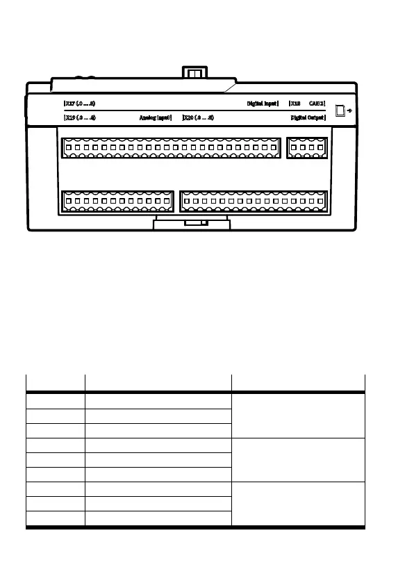
11 Direct connections, bottom
[X19] Analogue input Digital output [X20]
[X17] Digital input CAN 2 [X18]
0.1 1.1 2.1 3.1 4.1 5.1 6.1 7.1 1 2 3 4
0.1 1.1 3.12.1 0.1 1.1 2.1 3.1 4.1 5.1 6.1 7.1
Fig. 21
11.1 Digital inputs [X17]
The digital inputs, configured in 3-wire connection technology, are not
galvanically separated. The ground potential for all inputs relates to GND
of the power supply [X1].
Always use 3 adjacent terminals when connecting a sensor with a
3-wire configuration.
Terminal
Port Comments
X17.0.1 24 VDC
Connection for digital sensor1
(1 kHz, IEC type1)
X17.0.2 Signal1 / home signal for drive A
X17.0.3 GND logic
X17.1.1 24 VDC
Connection for digital sensor2
(1 kHz, IEC type1)
X17.1.2 Signal2 / home signal for drive C
X17.1.3 GND logic
X17.2.1 24 VDC
Connection for digital sensor3
(1 kHz, IEC type1)
X17.2.2 Signal 3
X17.2.3 GND logic
 Loading...