3 Application Interface
Copyright © Fibocom Wireless Inc. 23
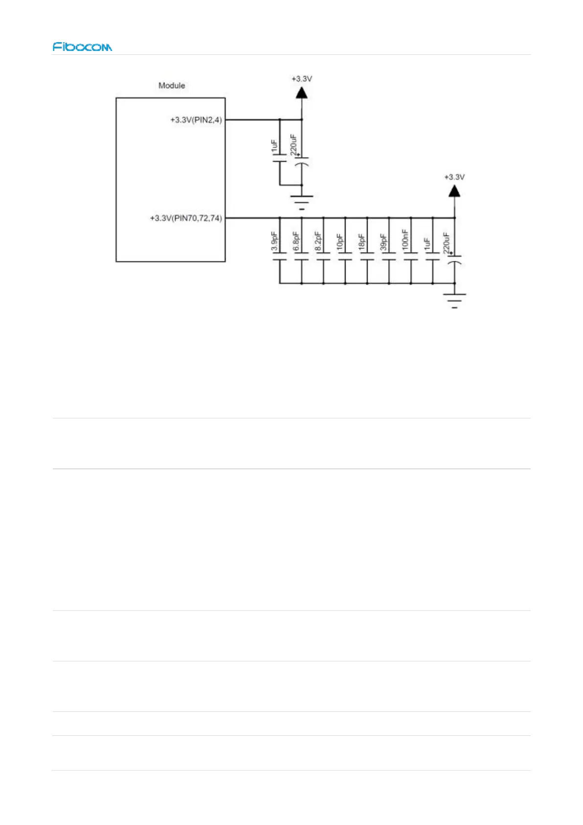
Figure 4. Power supply design
The filter capacitor design for power supply as shown in the following table:
Table 8. The filter capacitor design for power supply
Voltage-stabilizing
capacitors
Reduce power fluctuations of the
module in operation, requiring
capacitors with low ESR.
LDO or DC/DC power supply requires
the capacitor with no less than 440uF
in the power supply voltage range.
Filter out the interference generated
from the clock and digital signals
700/800, 850/900 MHz
frequency band
Filter out low frequency band RF
interference
Filter out medium/high frequency band