6 Structure Specification
Copyright © Fibocom Wireless Inc. 65
6.5 M.2 Card Assembly
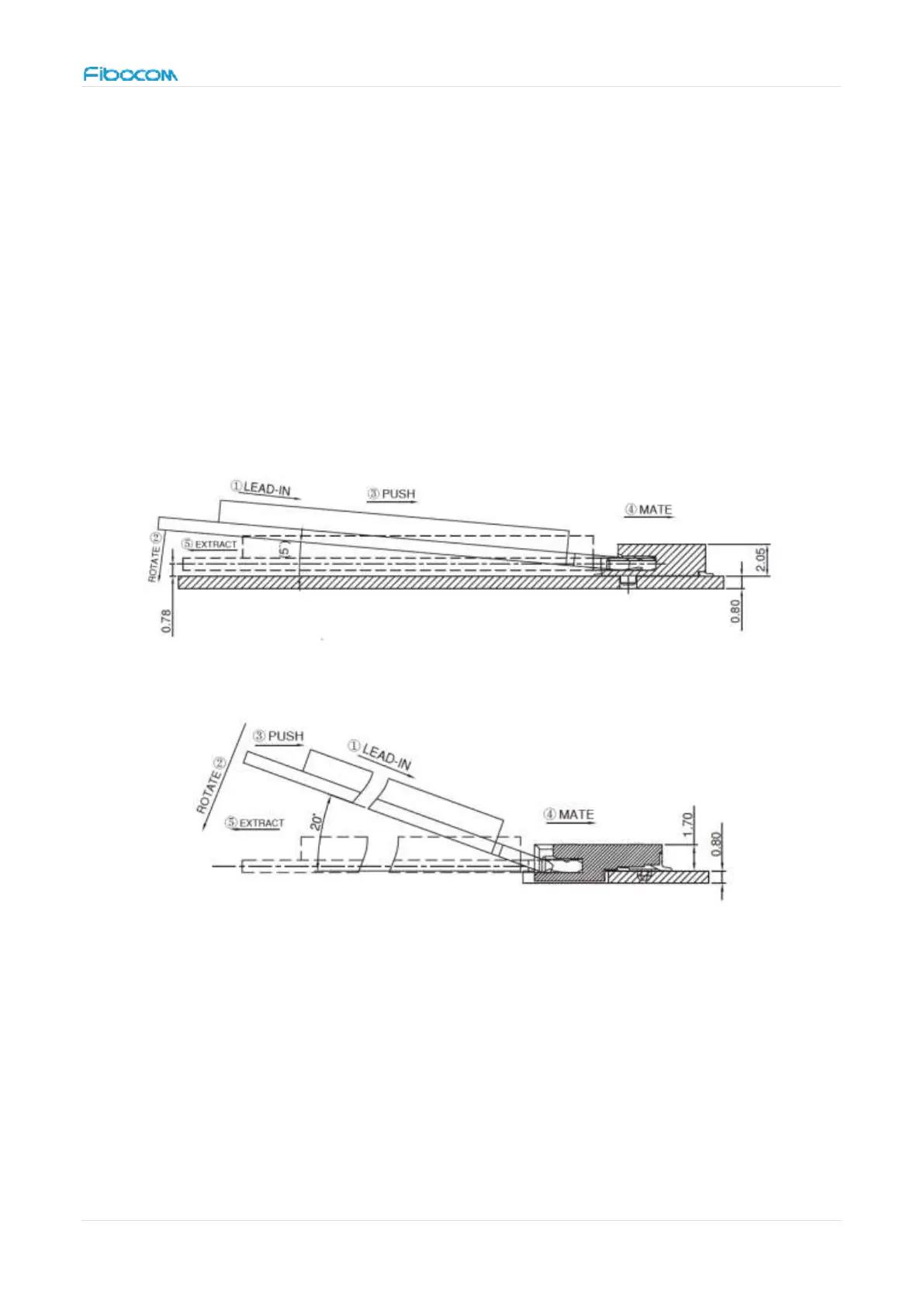
6.5.1 Card Insertion
Angled insertion is allowable and preferred; intent is to minimize the insertion and
extraction force. The minimum angle of insertion is 5 ° . For APCI0144-P001A, the
maximum angle of insertion is 5°. For APCI0026-P001A, the maximum angle of insertion is
20°. Refer to Figure 30 and Figure 30 to insert and extract the module.
Figure 30. Angle of insertion for APCI0144-P001A
Figure 31. Angle of insertion for APCI0026-P001A
6.5.2 Mid-mount Connection with Single-Sided Module
Stack-up Mid-mount (In-line) single-sided module is shown in Figure 32. The maximum
height of components is 1.5 mm.