EasyManuals Logo

Fibocom FM101-GL User Manual

Fibocom FM101-GL
78 pages
To Next Page IconTo Next Page
To Previous Page IconTo Previous Page
Page #31 background imageLoading...
Page #31 background image
3 Application Interface
Copyright © Fibocom Wireless Inc. 29
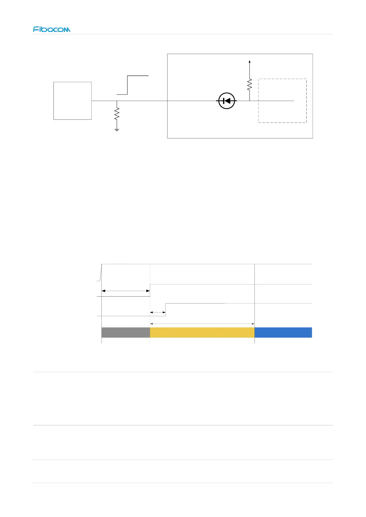
Figure 6. Circuit for module start-up controlled by AP
3.3.1.2 Start-up Timing Sequence
When power supply is ready, the PMU of module will power on and start initialization
process by pulling high FCPO# signal. After about TBDs, module will complete initialization
process. The start-up timing is shown in Figure:
+3.3V
tpr
RESET#
ton
Module State
Initialization
Activation(AT Command Ready)
FCPO#
typical TBDs
OFF
Figure 7. Timing control for start-up
Index
Min.
Recommende
d
Max.
Comment
t
pr
0ms
-
-
The delay time of power supply rising from 0V up
to
POWER_ON/OFF#
PMU
Module
AP
GPIO
(Reserved)
FULL_CARD_POWER_OFF#
(3.3/1.8V) (1.8V)
100KΩ
22KΩ

Questions and Answers:

Question and Answer IconNeed help?

Do you have a question about the Fibocom FM101-GL and is the answer not in the manual?

Fibocom FM101-GL Specifications

General IconGeneral
BrandFibocom
ModelFM101-GL
CategoryWireless modules
LanguageEnglish

Related product manuals