6
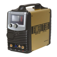
FIGURE 1:
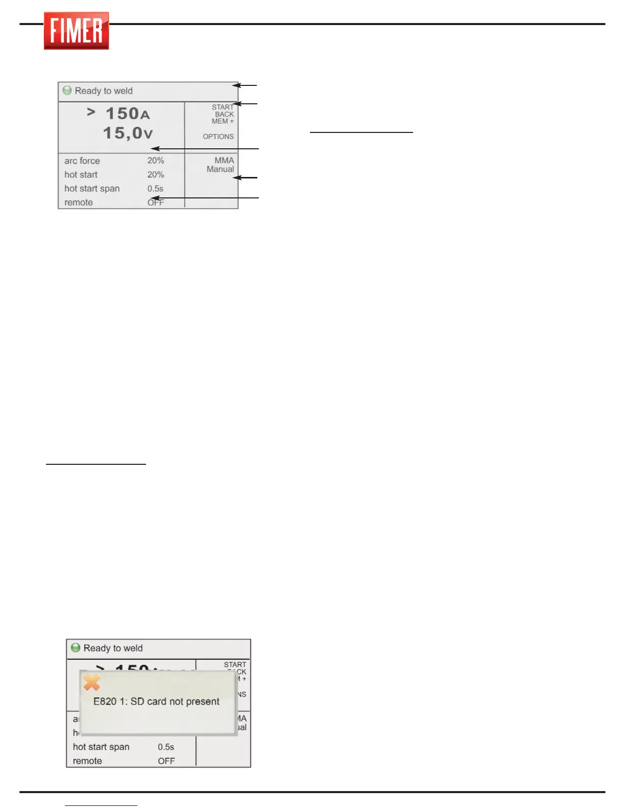
1. Graphic display:
The 5,7’’ colour screen displays different
screens, according to the welding mode or
settings. In weld mode the display is divided
into five principal:
Part 1: Machine status
Part 2: Meaning of the active buttons
(buttons 2, 3, 4, 5,6 di fig.1)
Part 3: Size values set
Part 4: Type of process selected
Part 5: Indicates the values that can be set
for the various welding settings (to change
the values select using switch 10 and
confirm the selection by pressing the same
switch; the value will be highlighted in a
contrasting colour. The values can be
changed by turning the switch, to confirm
the new value press the switch again. 10).
Highlighted value:
Indicates the parameter
that is being changed using switch 10.
DISPLAYS:
- When the screen comes on, the Fimer logo
will appear and the Firmware revisions will load.
CONTROL BUTTONS:
(2, 3, 4, 5,6 in fig.1)
Each control button is associated with a
specific function shown on the display.
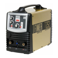
7. SD slot: this slot, covered with a rubber
cap, contains the SD-Card provided with the
machine; without the card, the machine will
be inactive and a warning message will
appear on the screen.
8. USB port: only for technical assistance.
9. Knob for setting the main welding
parameter: the main welding parameter can
be set with this knob:
Welding MMA/TIG:
sets the welding current.
11. Air grills (must never be obstructed).
12. “-” dinse front connector: negative
pole inlet.
Connection socket TIG torch mode.
MMA Mode: Ground clamp
MIG Mode: Ground clamp
13. Connector for remote control.
14. “+” dinse front connector: positive
pole inlet.
MMA Mode:Electrode holder
TIG Mode:Ground clamp
MIG Mode with gas: Not used
15. Gas Outlet:
MMA Mode: inactive
TIG Mode: Gas connection to the welding torch
(Internal tap positioned on TIG GAS)
MIG Mode with gas: inactive (internal tap
positioned on MIG GAS)
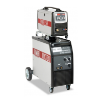
16. EUROCONNECTOR (SEPARATED
TROLLEY): quick connector for welding
torch. This connector is used to supply welding
gas to the torch, the electrical contacts of the
torch button and the welding current.
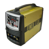
FIGURE 2:
17. ON-OFF switch: turns the machine on
and off.
18. Input cable: connection cable to the
mains power equipped.
19. Welding gas inlet
MMA Mode: Not used
TIG Mode: GAS connection to the cylinder
MIG Mode with gas: GAS connection to the
cylinder
20. Fuse
21.Connector for supplying power to the
liquid cooling system (Optional): Warning
the connector contains dangerous
voltages: NEVER use it for purposes other than
those for which it was specifically designed.
Part 1
Part 2
Part 3
Part 4
Part 5