Do you have a question about the FINE mechatronics FS-8000 and is the answer not in the manual?
Introduction to the FS-8000 weighing indicator and its applications.
Essential safety conditions for operating the weighing indicator.
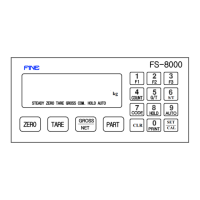
Detailed description of the FS-8000's front panel layout and components.
Explanation of the various indicator lamps on the front panel.
Instructions on operating the keys on the front panel.
Overview and identification of the connectors and controls on the rear panel.
Specifications for analog input and analog-to-digital conversion.
Specifications related to the digital display and interface.
General specifications including power, weight, and dimensions.
List and brief description of available optional functions.
Guidelines and precautions for installing the indicator.
List of parts included with the indicator for installation.
Information about stable load cells and their output.
Details on connecting the load cell connector.
Table showing load cell wire colors from different manufacturers.
Procedure for performing zero adjustment on the indicator.
Guide to adjusting dip switches for zero adjustment.
Methods to enter the span adjustment mode.
Detailed steps for performing span adjustment.
Steps 1-3 of span adjustment: division, weight, and zero check.
Steps 4-7 of span adjustment: standard weight, completion, and final checks.
Cause and adjustment for error codes ERR-01 through ERR-05.
Cause and adjustment for error codes ERR-55 and ERR-06.
Cause and adjustment for ERR-07, ERR-10, UL, and OL errors.
Instructions on how to access the set-up mode.
Details on navigating and using the set-up menu with examples.
Summary list of available functions and their settings.
Settings for basic weighing functions (F00).
Settings related to basic device functions (F10).
Settings for the control system (F20).
Settings for serial interface specifications (F30).
Settings for BCD output specifications (F50).
Settings for analog output specifications (F60).
Illustrations and examples of basic weighing functions.
Explanation of basic functions for connecting devices.
Further basic functions for devices including signal modes and input settings.
Manual/Auto modes and user-defined key functions for F1, F2, F3.
Settings for auto function, hold function, and nomination code.
Device identification, date/time modification, and basic zero check.
Settings for baud rate, parity, transmit mode, format, and interface wire.
Detailed information on RS-232C interface, signal format, and stream mode.
Explanation of the data format used in RS-232C communication.
Diagram of RS-232C circuit and a sample computer program.
Signal and data format specifications for the current loop interface.
Setup for BCD output, including weight selection and polarity.
Circuit diagrams and explanations for BCD output.
Details on RS-422/485 serial interface, signal format, and circuit.
Setup for Analog Out, including weight selection, standard, and polarity.
Specifications and calibration for 0-10V analog output.
Specifications and calibration for 4-20mA analog output.
Printer selection options and examples of print sheets.
Settings for printer paper quantity and sub-total printing mode.
Details of the BCD input circuit and connector pinout.
| Brand | FINE mechatronics |
|---|---|
| Model | FS-8000 |
| Category | Accessories |
| Language | English |