24
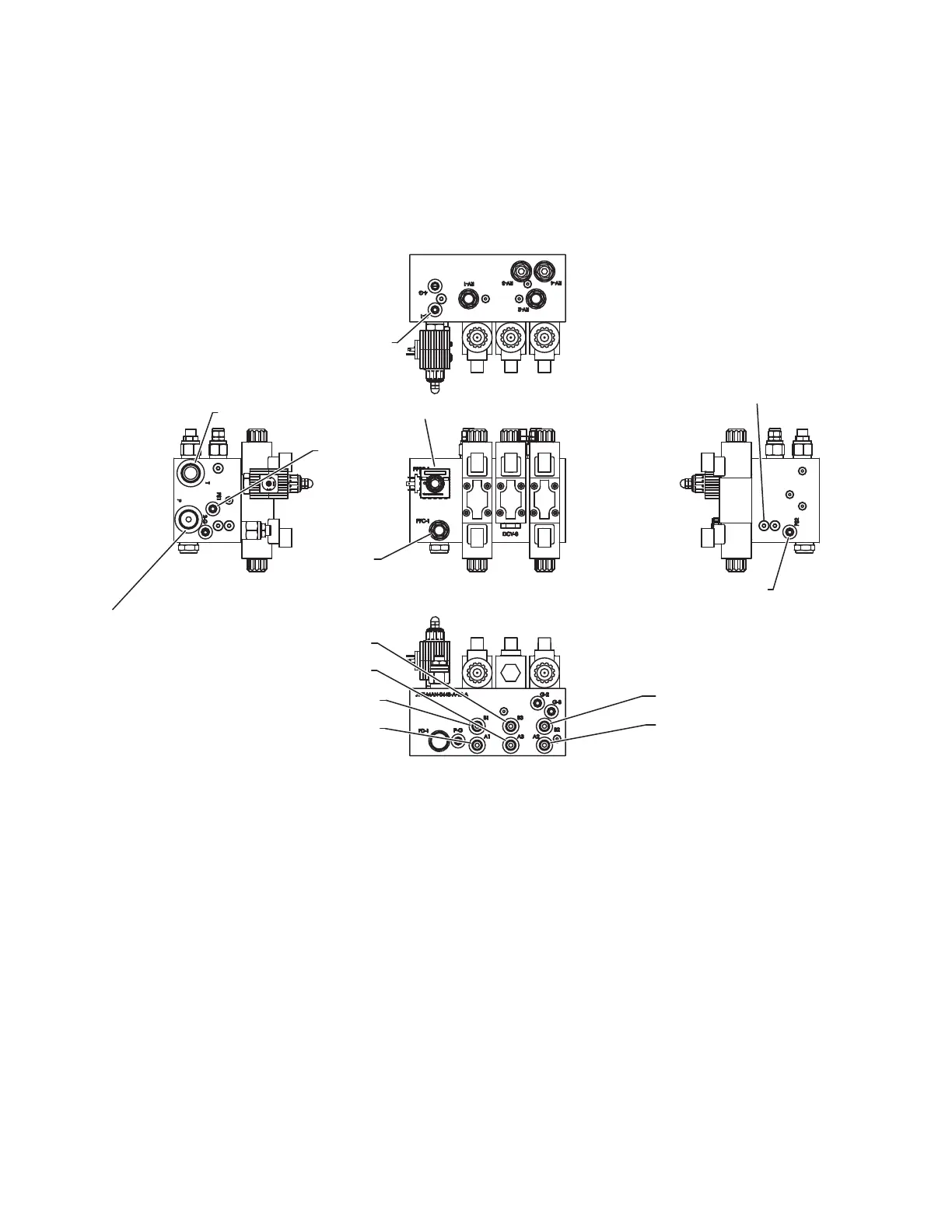
DESCRIPTION OF VALVE SECTIONS
The illustration below shows the valve block and different hydraulic circuits. Each circuit is
controlled by two valves, with the exception of the hose reel (middle) circuit. The floor and airlock
valves are directional valves that can be manually stroked by inserting a small rod or screwdriver
into the hole on top or bottom of the solenoid. The hose reel circuit is controlled by a two-position
ON/OFF valve and its solenoid can only be actucated in one direction by inserting a small rod or
screwdriver into the hole on top of the solenoid.
A. AIRLOCK
The right valve section of the manifold runs the airlock. The spool in the valve is factory-set so the
airlock turns at about 16 RPM. The speed of the Airlock can be adjusted using PFC-1. There is a
pressure switch on the forward circuit that is set for 2,400 psi (16,547 kPa) that triggers the auto-
reverse function on the airlock. Normal rotation of the airlock is clockwise if viewing from the driver
side of the machine.
B. FLOOR (DRAG CONVEYOR)/FEED ROLL
The left valve section controls the floor and feed roll speed. It is an electrically-driven proportional
valve that is controlled by the floor increase (FLOOR INC) and floor decrease (FLOOR DEC)
buttons on the keypad of the main control panel and the toggle switch on the radio remote
trasnmitter. Pressing the buttons or toggling the switch up or down varies the input voltage to
the solenoid and moves the spool in the valve accordingly, allowing more or less oil flow to
the floor and feed roll. There is a pressure switch on the forward circuit that is set for 2,050 psi
(14,134 kPa) that triggers the auto-reverse function on the floor.
#6 CONNECT TO FLOOR
MOTOR (NON-DRIVE SIDE)
#6 CONNECT TO FLOOR
MOTOR (DRIVE SIDE)
#6 CONNECT TO AIR LOCK
MOTOR (NON DRIVE SIDE)
#6 CONNECT TO AIR LOCK
MOTOR (DRIVE SIDE)
#6 CONNECT TO HOSE
REEL (NON-DRIVE SIDE)
#6 CONNECT TO HOSE
REEL (DRIVE SIDE)
#12 HOSE COMING
FROM HIGH PRESSURE
FILTER
#12 HOSE GOING TO
HYD COOLER
FLOOR
PRESSURE
SWITCH
AIR LOCK
PRESSURE SWITCH
FLOOR PRESSURE GAUGE
FLOOR
HOSE
REEL
AIRLOCK
PFC-1
PPFC-1
AIR LOCK
PRESSURE GAUGE
Valve Block
 Loading...