17
SET PLUS 2.0 - SET 2.0
Luogo d’installazione
Il prodotto deve essere installato all’interno di
un edicio e deve essere posizionato tenendo
conto degli spazi necessari all’esecuzione
delle operazioni di manutenzione (vedi tabella
e disegno).
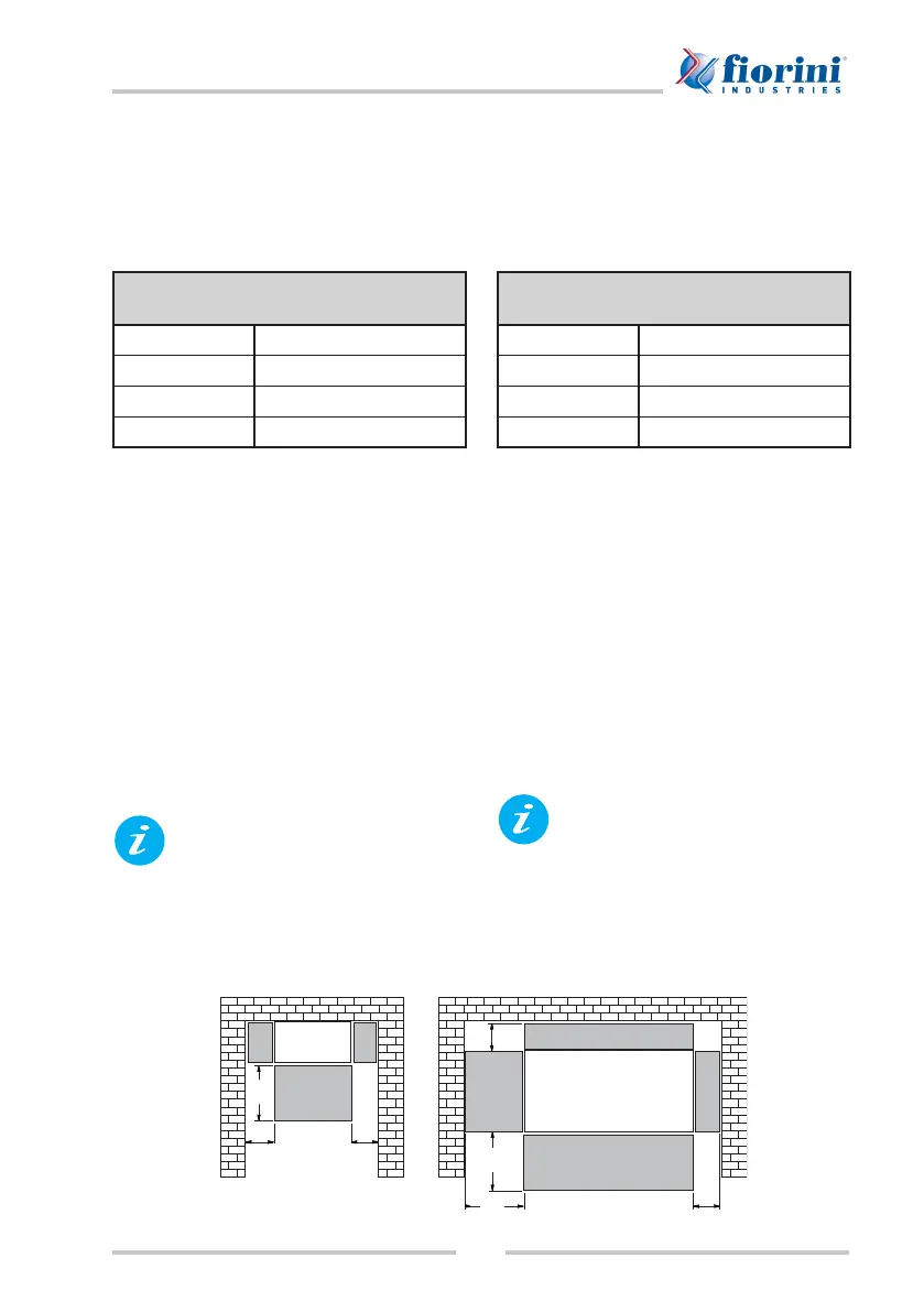
Misure spazi liberi per manovra
A 1000 mm
B 1000 mm
C 500 mm
D 100 mm
Se si è scelto un modello pensile (SET PLUS
2.0 - 25/35/40): vericare che la parete su cui
sarà installato il prodotto sia perfettamente
verticale e capace di sostenere il peso del
prodotto stesso e del suo contenuto (vedi
targhetta caratteristiche tecniche). Per il
montaggio seguire le istruzioni descritte al
par. “Fissaggio a parete”.
Se si è scelto un modello con struttura auto-
portante (SET 2.0 - 60/70/80/100/120/200):
vericare che la supercie su cui sarà installa-
to il prodotto sia piana e capace di sostenere
il peso del prodotto stesso e del suo conte-
nuto (vedi targhetta caratteristiche tecniche).
Prima di procedere con
l’installazione si consiglia di
rimuovere i pannelli di rivestimento
per agevolare le operazioni
descritte ai paragra successivi
ed evitare di danneggiarli (vedi
par. “Smontaggio/montaggio dei
pannelli di rivestimento”).
Installation site
Position the unit inside a building leaving a
sufcient space all around for maintenance
(see table and drawing).
Free spaces to leave all around the unit
A 1000 mm
B 1000 mm
C 500 mm
D 100 mm
If you have a wall-mounted model (SET
PLUS 2.0 - 25/35/40), ensure that the wall
where the product shall be installed is vertical
and has a sufcient load-bearing capacity for
the product and its content (see data plate).
For the installation, obey the instructions
provided in paragraph “Wall mounting”.
If you have a model with self-supporting
structure (SET 2.0 - 60/70/80/100/120/200),
ensure that the oor on which the product
shall be installed, is at and has a sufcient
load-bearing capacity for the product and its
content (see data plate).
Prior to proceeding with the
installation, we recommend
removing the protection panels
as explained in par. “Removing/
assembling the protection panels”
to avoid damaging them during
assembly.
A
C
C
DD
SET 2.0
60/70/80/100/120/200
SET PLUS
2.0 - 25/40
A