39
SET PLUS 2.0 - SET 2.0
Annex 3:
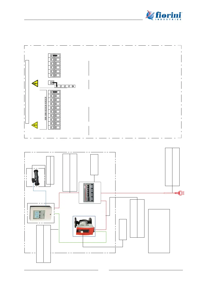
SET 2.0 - 60/70/80/100/120/200 wiring diagram
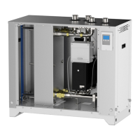
TERMINAL BOARD WIRING DIAGRAM
230 VAC
line side
Probe side
max. 12 V
Danger
Warning
SPECIAL CONTROLLER FUNCTIONS
TO ENABLE:
6.1.1 Type of pump = 0-10V
6.1.2 Pump = Proe 7
6.1.3 Output signal = Normal
CAN
CANVFS2VFS1
S6
+
V2 V1 S5 S4 S3 S2 S1
-
R3 R3IR2R1L N
PELV
Flow meter --> LFWC
VFS1 connector
Power supply
824080021 - FROR 3x1.5 wire
L --> Phase
N --> Neutral
825010586
SET E.B. 0-10V
Pump --> E.B. QF1
824080021 - FROR 3x1.5 wire
Phase --> brown
Neutral --> blue
LFWC controller --> QF2 E.B.
824080094 - FROR 3x1 wire
L --> 206
N --> 207
0-10V control --> LFWC
824080065 - bipolar shielded wire
- --> GND (brown)__I_
V1 --> Sign. 0-10V (white) IN
IF module
Ext. Min/Ext. Off
230VAC 50-60Hz power lines
Use right side of terminal board for
connection
!
Terminal: Connection for:
L Mains phase conductor L
N Mains neutral conductor N
R1 Relay 1
R2 Relay 2
R3 Relay 3 (normally closed)
R3I Relay 3 (normally open)
The PE protective conductor shall be
connected to the PE metal terminal
board!
Low voltage max. 12VAC/DC
Use left side of terminal board for
connection
!
Terminal: Connection for:
S1 Circulation (opt.)
S2 Cold water (opt. see below)
S3 Primary circuit (opt.)
S4 High storage (opt.)
S5 Medium storage (opt.)
V1 0-10V/PWM primary pump
signal
V2 0-10V/PWM signal (opt.)
S6 Primary circuit return (opt.)
- Probe bridge
VFS1 Cold water inlet
VFS2 optional
The polarity of probes PT1000 can be
selected freely.
Relay connections change based on the additional functions selected.
Connect grounding probe (1-6) with probe attached to terminal board (-).
VFS probes shall be connected to the power outlet on the control panel.
Probe 2 / Cold water: when not connected, no probe is set to a temperature of
10°C.