35
SET PLUS 2.0 - SET 2.0
Annex 1:
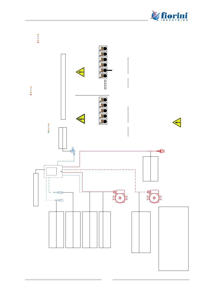
SET PLUS 2.0 - 25/35/40 wiring diagram
L N R N R
_
VFS
V1 -S1 S2
UPM3 HYBRID PUMP CONFIGURATION:
Press ➲ once to verify the pump conguration ( ).
If the conguration does not match, press ➲ again and hold it pressed down for more than 2 seconds.
Press ➲ several times until the LED bar for PWM conguration at maximum curve illuminates ( ).
Wait 10 seconds. The LEDs stop blinking and the new conguration is stored in memory.
If the pump conguration is correct, the pump shall be in the stand-by mode and the rst LED shall be green
and blinking ( ).
TERMINAL BOARD WIRING DIAGRAM
230 VAC
line side
Probe side
max. 12 V
Danger
Warning
Mains
Sensors
* PELV connection
230VAC 50-60Hz power lines
Use left side of terminal board for
connection!
Terminal: Connection for:
L Mains phase conductor L
N Mains neutral conductor N
R Relay (normally open)
N Mains neutral conductor N
R Relay (normally closed)
The PE protective conductor shall be
connected to the PE metal terminal
board!
Low voltage max. 12VAC/DC
Use right side of terminal board for
connection!
Terminal: Connection for:
S1 Circulation (opt.)
S2 Storage (opt.)
V1 0-10V/PWM primary pump
signal
- 0-10V/PWM signal
The polarity of probes PT1000 can be
selected freely.
Relay connections change based on the additional functions selected.
VFS probes shall be connected to the power outlet on the control panel.
Warning
Bridge of probe mass to PE protective conductor is required
(PELV connection).
SOREL controller
PROBE PT1000 (optional)
CIRCULATION
S1 --> Red
- --> White
PROBE PT1000 (optional)
STORAGE
S2 --> Red
- --> White
Flow meter
VFS connector
PUMP --> SFWC
Phase --> L
Neutral --> N
Ground --> *PELV
PWM
V1 --> Brown
- --> Blue
Power supply
Phase --> L
Neutral --> N
Ground --> *PELV
(optional)
RECIRCULATING PUMP --> SFWC
Phase --> R
Neutral --> N
Ground --> *PELV
SPECIAL CONTROLLER FUNCTIONS TO ENABLE:
6.1.1 Type of pump = PWM
6.1.2 Pump = Heating
6.1.3 Output signal = reversed
(optional)
6.3.1 Relay 1 = Circulation