37
SET PLUS 2.0 - SET 2.0
Annex 2:
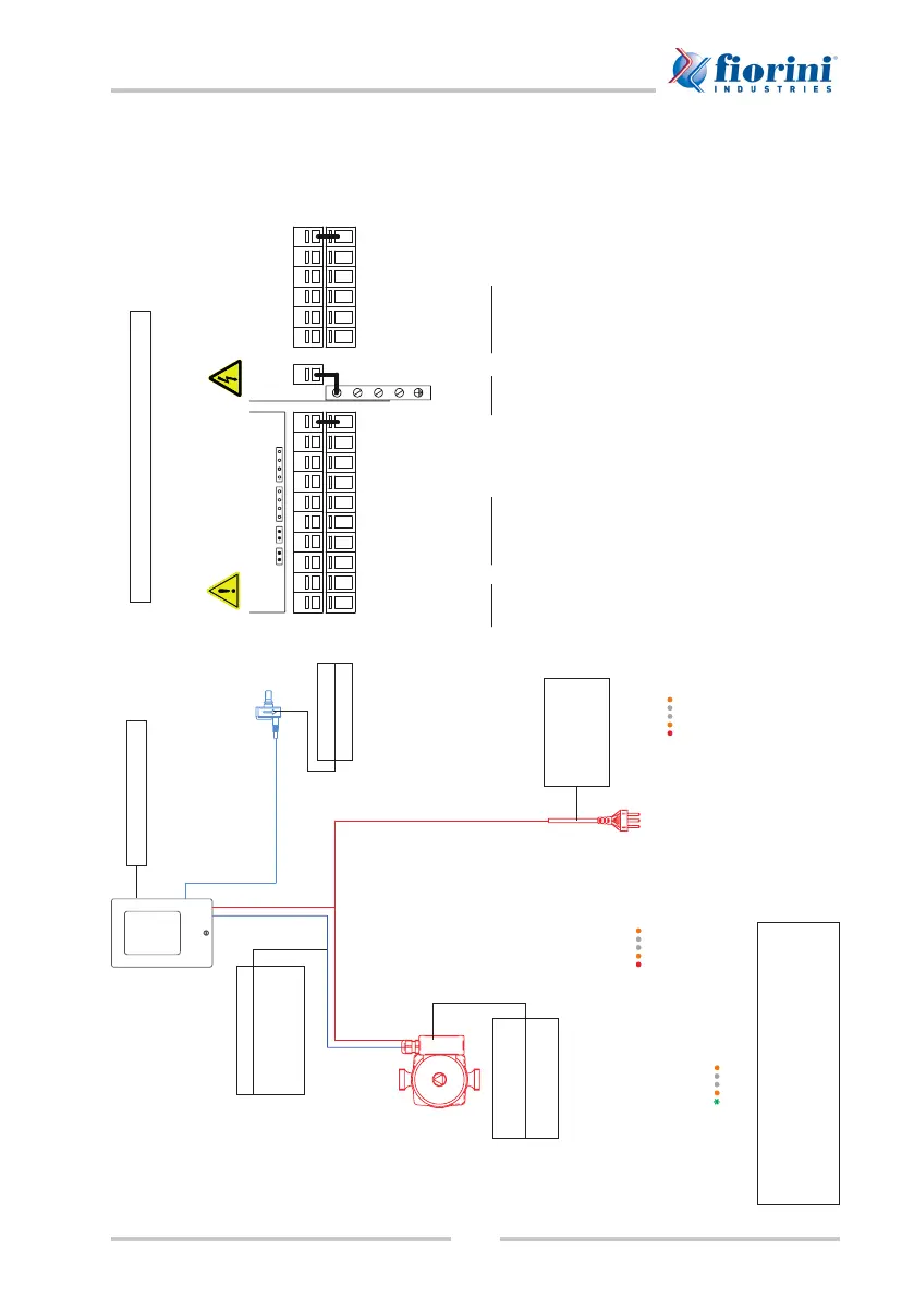
SET PLUS 2.0 LFWC - 25/35/40 wiring diagram
CANCAN VFS2 VFS1
S6
+
V2 V1 S5 S4 S3 S2 S1
-
R3 R3I R2 R1 LN
PELV
UPM3 HYBRID PUMP CONFIGURATION::
Press ➲ once to verify the pump conguration ( ).
If the conguration does not match, press ➲ again and hold it pressed down for more than 2 seconds.
Press ➲ several times until the LED bar for PWM conguration at maximum curve illuminates ( ).
Wait 10 seconds. The LEDs stop blinking and the new conguration is stored in memory.
If the pump conguration is correct, the pump shall be in the stand-by mode and the rst LED shall be
green and blinking ( ).
TERMINAL BOARD WIRING DIAGRAM
230 VAC
line side
Probe side
max. 12 V
Danger
Warning
SOREL CONTROLLER
PUMP --> LFWC
Phase --> L
Neutral --> N
Ground --> *PELV
PWM
V1 --> Brown
- --> Blue
black wire NC and insulated
Power supply
Phase --> L
Neutral --> N
Ground --> *PELV
SPECIAL CONTROLLER FUNCTIONS TO ENABLE:
6.1.1 Type of pump = PWM
6.1.2 Pump = Heating
6.1.3 Output signal = reversed
Flow meter
VFS1 connector
230VAC 50-60Hz power lines
Use right side of terminal board for
connection
!
Terminal: Connection for:
L Mains phase conductor L
N Mains neutral conductor N
R1 Relay 1
R2 Relay 2
R3 Relay 3 (normally closed)
R3I Relay 3 (normally open)
The PE protective conductor shall be
connected to the PE metal terminal board!
Lowe voltage max. 12VAC/DC
Use left side of terminal board for
connection
!
Terminal: Connection for:
S1 Circulation (opt.)
S2 Cold water (opt. see below)
S3 Primary circuit (opt.)
S4 High storage (opt.)
S5 Medium storage (opt.)
V1 0-10V/PWM primary pump
signal
V2 0-10V/PWM signal (opt.)
S6 Primary circuit return (opt.)
- Probe bridge
VFS1 Cold water inlet
VFS2 optional
The polarity of probes PT1000 can be
selected freely.
Relay connections change based on the additional functions selected.
Connect grounding probe (1-6) with probe attached to terminal board (-).
VFS probes shall be connected to the power outlet on the control panel.
Probe 2 / Cold water: when not connected, no probe is set to a temperature of
10°C.