2
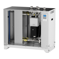
SET PLUS 2.0 - SET 2.0
INDICE
Simbologia ...........................................................................3
Osservazioni ........................................................................4
Descrizione e scopo del prodotto ........................................5
Modello e tipo .................................................................. 5
Marcatura CE ..................................................................6
Conformità alle Direttive Europee........................................6
Identicazione......................................................................6
Pericoli e precauzioni ..........................................................7
Dati tecnici ........................................................................... 8
Dimensioni e caratteristiche tecniche ..............................8
Descrizione componenti e attacchi per l’installazione ... 10
Schema d’installazione in abbinamento a
termoaccumulo .................................................................. 12
Installazione ed Uso ..........................................................16
Imballaggio del prodotto ............................................... 16
Movimentazione del prodotto ........................................16
Luogo d’installazione .....................................................17
Fissaggio a parete
(solo per SET PLUS 2.0 - 25/35/40) .............................18
Smontaggio/montaggio dei pannelli di rivestimento ...... 19
Installazione ..................................................................20
Collegamento elettrico ..................................................21
Messa in servizio ...........................................................22
Centralina ..........................................................................23
Display della centralina .................................................23
Programmazione della centralina ..................................25
Manutenzione .................................................................... 28
Manutenzione del modulo SET .....................................28
Pulizia periodica scambiatore
(solo da personale addetto) ..........................................29
Manutenzione della centralina ......................................31
Smaltimento.......................................................................31
Eventuali anomalie e possibili rimedi.................................32
Allegato 1: .........................................................................34
Schema elettrico SET PLUS 2.0 - 25/35/40 .................. 34
Allegato 2: .........................................................................36
Schema elettrico SET PLUS 2.0 LFWC - 25/35/40 .......36
Allegato 3: .........................................................................38
Schema elettrico SET 2.0 - 60/70/80/100/120/200 ......38
Schema elettrico quadro di potenza .................................. 40
CONTENTS
Symbols ...............................................................................3
General warnings ................................................................4
Product description and intended use .................................5
Model and type ................................................................5
CE-marking .....................................................................6
Compliance with EU Directives ...........................................6
Identication ........................................................................6
Hazards and warnings .........................................................7
Technical data......................................................................8
Dimensions and specications ........................................ 8
Description of components and ttings for installation ..10
Installation diagram when coupled to a
hot water storage tank ....................................................... 12
Installation and Use ........................................................... 16
Packaging .....................................................................16
Handling the product .....................................................16
Installation site...............................................................17
Wall-mounting
(only for SET PLUS 2.0 - 25/35/40) ..............................18
Removing/assembling the protection panels ................19
Installation .....................................................................20
Electrical connection .....................................................21
Putting into service ........................................................ 22
Controller ........................................................................... 23
Controller display ..........................................................23
Programming the controller ........................................... 25
Maintenance ...................................................................... 28
Maintenance of the SET module ................................... 28
Heat exchanger periodic cleaning
(only authorized staff) ....................................................29
Maintenance of the controller ........................................ 31
Disposal .............................................................................31
Troubleshooting ................................................................. 33
Annex 1: ...........................................................................35
SET PLUS 2.0 - 25/35/40 wiring diagram .....................35
Annex 2: ...........................................................................37
SET PLUS 2.0 LFWC - 25/35/40 wiring diagram ..........37
Annex 3: ...........................................................................39
SET 2.0 - 60/70/80/100/120/200 wiring diagram ...........39
Power board wiring diagram ..............................................40