EasyManua.ls Logo

Fire-Lite 411 User Manual

Fire-Lite 411
64 pages
To Next Page IconTo Next Page
Page #1 background imageLoading...
Page #1 background image
Digital Alarm
Communicator/Transmitter
411
P/N 50921:E ECN 08-879
E
Document #50921
12/09/2008 Rev.
© 2009

Table of Contents

Question and Answer IconNeed help?

Do you have a question about the Fire-Lite 411 and is the answer not in the manual?

Fire-Lite 411 Specifications

General IconGeneral
BrandFire-Lite
Model411
CategoryFire Alarms
LanguageEnglish

Summary

Fire Alarm System Limitations

System Performance Limitations

Discusses limitations of smoke/heat detectors and how smoke may not reach sensors.

Maintenance and Malfunction Causes

Addresses common causes of malfunction like inadequate maintenance and testing.

Installation Precautions

System Testing and Environmental Considerations

Covers reacceptance testing after changes and environmental operating ranges.

Electrical and Static Handling Procedures

Details precautions for wiring, grounding, and handling static-sensitive components.

Chapter 1: Product Description

Digital Communicator Specifications

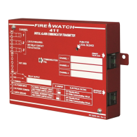
Details specifications including circuits, power requirements, and interfaces.

Product Overview and Features

Technical Specifications

Power Input and Connections

Specifies power requirements (12/24 VDC) and ground connections.

Channel and Relay Specifications

Details input channel configurations and Form-C relay capabilities.

Circuitry and Controls

Digital Communicator Operation

DACT Functional Overview

Explains DACT functions like line seizure, dialing, and tone recognition.

Operational Modes

Mode Descriptions

Defines Normal, Real-Time Clock, Program, Troubleshoot, and Default modes.

Chapter 2: Installation

Operating Power Requirements

Details the 12 VDC or 24 VDC power connections and configuration.

Input Channel Configuration

Explains the three input channels, their supervision, and Style B circuits.

Output Circuits and Relays

Programmable Relay Functions

Describes the Form-C relay's programmability for various conditions.

Telephone Circuitry and Wiring

Optional Programmer Usage

Programmer Functions and Connectivity

Outlines the programmer's role in switching modes and accessing functions.

UL Power-Limited Wiring Requirements

Power Input and Wiring Restrictions

Stresses that power supplied must be power-limited and non-power-limited wiring is prohibited.

Chapter 3: Modes of Operation

Normal Mode Operation

Describes Normal Mode as the standard state, monitoring status and reporting to central station.

Normal Mode Operations

Real Time Clock Mode

Real Time Clock Mode Programming

Entering Time Values

Details the process of entering the 24-hour time in military format.

Chapter 3: Program Mode

Program Mode Entry and Notice

Explains how to enter Program Mode and provides important notices to users.

Program Mode: Primary Phone Number

Primary Central Station Phone Number Entry

Details the programming of primary phone numbers using addresses 00-19.

Program Mode: Communication Formats

Primary Station Communication Format Selection

Describes selecting the communication format for the primary phone number (address 20).

Program Mode: Event Codes - Primary

Program Mode: Account Codes and Test Times

Program Mode: Secondary Phone Number

Secondary Station Phone Number Entry

Details programming of secondary phone numbers using addresses 30-49.

Program Mode: Secondary Communication Format

Secondary Station Communication Format Selection

Describes selecting the communication format for the secondary phone number (address 50).

Program Mode: Secondary Account and Test Times

Program Mode: Secondary Test Interval and Delays

Communicator Enable/Disable

Enables or disables communication to the central station (address 64).

Input Channel Function Selections

Assigns functions (Fire Alarm, Trouble, etc.) to input channels (addresses 65-67).

Program Mode: Input Channel Timers and Phone Settings

Program Mode: Relay Functions and Trouble Calls

Output Relay Function Selections

Programs the output relay to activate for specific conditions (address 88).

Trouble Call Limit Feature

Limits the number of trouble calls sent to the central station (address 89).

Default and Troubleshoot Modes

Default Mode Operation

Describes returning the communicator to factory default program settings.

Troubleshoot Mode and Line Testing

Explains accessing Troubleshoot Mode and testing telephone lines.

Chapter 4: Central Station Communications

Communicator to Central Station Reporting

Details how the communicator sends system status reports to central stations.

Central Station Communication Priorities

Transmittal Priority Levels

Lists events in descending order of priority for transmission.

Ademco Contact ID Event Code Description

Central Station Receiver Compatibility

Programming Sheets: Factory Defaults

Digital Communicator Factory Default Settings

Lists the factory default settings for various programming addresses.

Appendix D: Wire Requirements

Wire Specifications Table

Provides a table detailing wire type, gauge, and run length for communicator circuits.

Appendix E: Operational Modes Summary

Appendix F: Canadian Applications

Related product manuals