Do you have a question about the Fire-Lite ECC-50 and is the answer not in the manual?
Details the key features and modular design for system flexibility and expansion.
Details the specifications and connections for various input and output circuits.
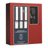
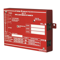
Describes the keypad layout, push-button controls, and LED indicators on the panel.
Identifies and describes the main control board, display board, cabinet, and batteries.
Details optional modules like audio amplifiers, expanders, and telephones.
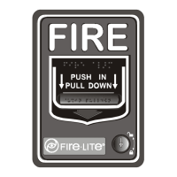
Specifies compliance requirements for low frequency sounders.
Provides guidelines for semi-flush or surface mounting the control panel cabinet.
Covers procedures for installing the backbox, including panel and chassis removal.
Details AC power and earth ground connection requirements for system operation.
Explains the specifications for the power-limited Class 2 auxiliary DC power output.
Describes CMD inputs, external audio input, NAC follower, and night ring connections.
Details the system's output circuits, including relays, speaker circuits, and NAC.
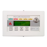
Provides wiring instructions for connecting the Local Operator Console.
Details wiring instructions for connecting the Remote Page Unit.
Provides wiring instructions for connecting the Remote Microphone.
Describes setup for distributed audio amplifiers and dipswitch settings.
Provides guidelines on using shielded cable for external device connections.
Explains the separation and routing requirements for power-limited wiring.
Details the installation process for optional circuit expander and audio amplifier modules.
Defines dipswitch settings for addressing external devices on the data bus.
Describes the main menu for programming and password options.
Details utilities for message recording and USB file transfers.
Covers viewing speaker circuit assignments, version, and history information.
Explains how to identify and install keypad labels for customization.
Details the functions of the 38 tactile push-button keys on the ECC-50/100.
Describes the meaning of various LED indicators on the main control panel.
Covers system monitoring, paging, manual message control, and alarm responses.
Basic setup guidelines for systems requiring up to 50W of audio power.
Basic setup guidelines for systems requiring up to 100W of audio power.
Setup guidelines for systems exceeding 100W, including FACP programming.
Introduces instructions and tables for calculating power supply currents.
Details calculations for the dedicated AC branch circuit requirements.
Explains how to calculate system current draws for standby and alarm conditions.
Provides steps to calculate battery size based on standby and alarm loads.
Describes audio isolator modules for short circuit isolation during alarm signaling.
| Type | Emergency Command Center |
|---|---|
| Power Supply | 120 VAC, 60 Hz, 3.0 A or 220/240 VAC, 50 Hz, 1.5 A |
| Mounting | Wall mount |
| Auxiliary Power Output | 24 VDC @ 0.5 A |
| Operating Temperature | 32°F to 120°F (0°C to 49°C) |
| Output Power | 50W |
| Zones | 8 |
| Speaker Circuit | Four Style Y (Class B) or Style Z (Class A) |
| Battery Capacity | Up to 18 Ah |
| Communication | RS-485 |
| Notification Appliance Circuits | Four Style Y (Class B) or Style Z (Class A) |
| Annunciators | Optional remote annunciators |
| Relays | One Form-C trouble relay, one Form-C alarm relay |