44 Emergency Command Center Manual — P/N LS10001-000FL-E:D 9/3/2014
Installation ECC-RPU Remote Page Unit
2.8 ECC-RPU Remote Page Unit
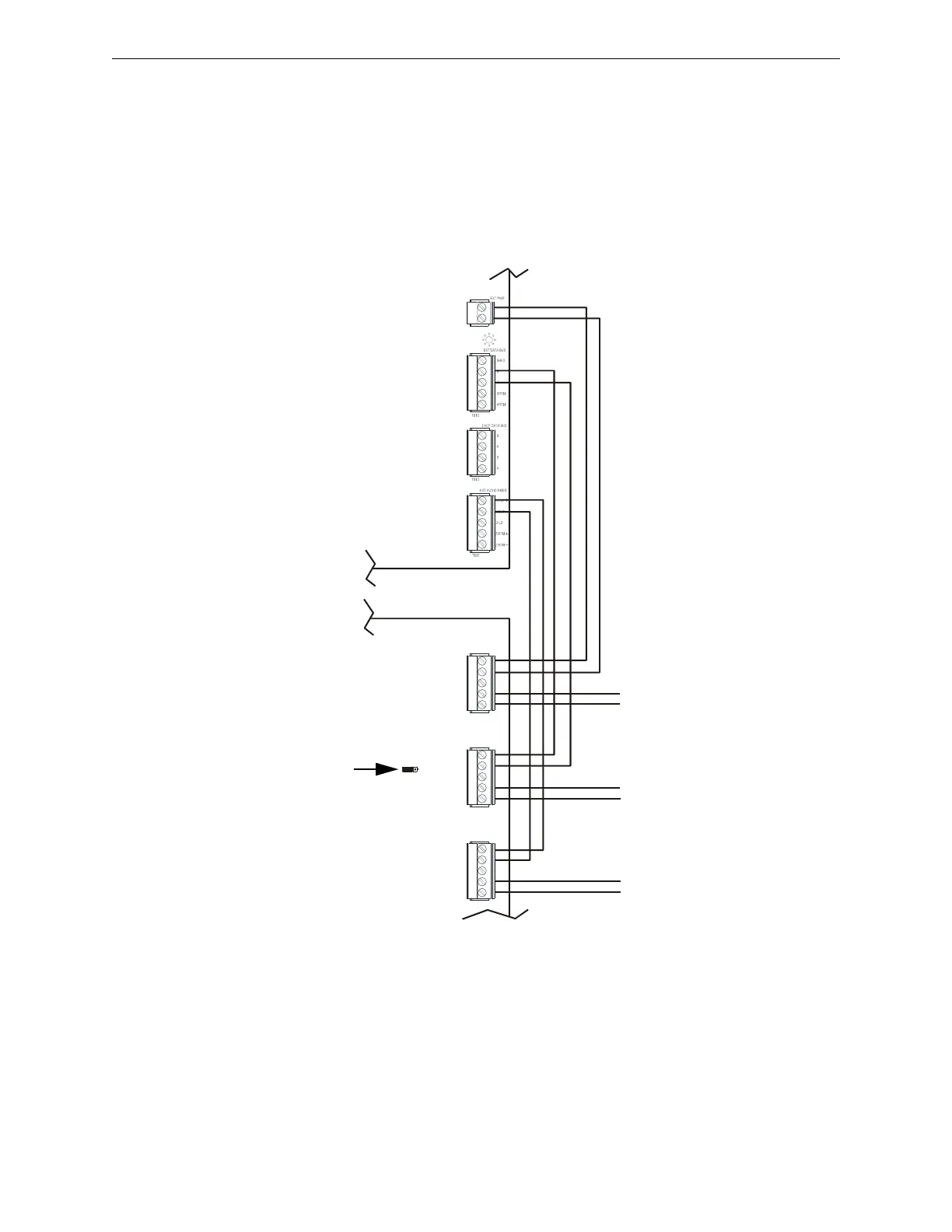
Connections are made from TB24, TB12, and TB22 on the ECC-50/100 main control board to
TB1, TB3, and TB2 on the RPU. If the ECC-RPU is the last device on the audio and data bus
chain, signal terminations are required. For the external data bus, a removable jumper must be on
pins 1 and 2 of JS4. If the ECC-RPU is not the last device, the jumper must be on pins 2 and 3 of
JS4 as shown below. For the external audio riser, when the ECC-RPU is the last device, termina-
tion ELR-15K must be connected to pins 4 and 5 on TB2. T-taps and multiple home runs to the
main control board are not allowed for the external data bus or the external data riser.
main control board
RPU board
TB24
TB12
TB22
TB1
TB3
TB2
external operator interface power - 24VDC
external
data bus
external
audio
riser
to next operator
interface or amplifier
r
p
u
w
i
r
e
b
.
w
m
f
Figure 2.24 Remote Page Unit Wiring (Class B/Style Y)
to next operator
interface or amplifier
to next operator
interface or amplifier
JS4
(shown jumpered
on pins 2 and 3)