14 Emergency Command Center Manual — P/N LS10001-000FL-E:D 9/3/2014
Product Description Input/Output Circuit Specifications
1.2 Input/Output Circuit Specifications
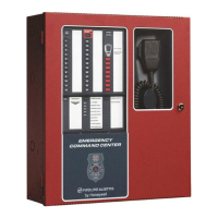
1.2.1 ECC-50/100 Main Control Board
AC Power - TB15
ECC-50/100: 120 VAC, 60 Hz, 3.5 amps (HOT, NEU)
ECC-50/100E: 240 VAC, 50 Hz, 2.0 amps (HOT=HotLeg1, NEU=HotLeg2)
Wire size: minimum #14 AWG (2.00mm
2
) with 600 V insulation.
Battery (lead acid only) - J7
Maximum Charging Circuit: Normal Flat Charge - 27.3V @ 2.8 amps
Maximum Charger Capacity: 26 Amp Hour battery. (ECC cabinet holds max. 18 Amp Hour Bat-
tery.
Minimum Battery Size: 12 Amp Hour
MNS Active Relay - TB1
Form-C relay contact rating: 2.0 amps @ 30 VDC (resistive), 0.5 amps @ 30 VAC (resistive),
Form-C Trouble Relay - TB2
Form-C relay contact rating: 2.0 amps @ 30 VDC (resistive), 0.5 amp @ 30 VAC (resistive).
AC Loss Relay - TB3
Form-C relay contact rating: 2.0 amps @ 30 VDC (resistive), 0.5 amps @ 30 VAC (resistive),
NAC Output - TB19, Terminals 1 (B+), 2 (A+), 3 (A-), & 4 (B-)
One (1) Style Y (Class B) or Style Z (Class A) circuit
Power-limited circuitry (Class 2), supervised
Nominal operating voltage: 24 VDC
Maximum signaling current for special application power: 2.0 amps
Maximum signaling current for regulated power: 200mA
Current limit: fuseless, electronic, power-limited
Maximum wiring impedance: 1
End-Of-Line Resistor: 4.7 K, ½ watt, (P/N 71252) required for Style Y (Class B) operation
Refer to the Device Compatibility Document for listed compatible devices.
NAC Follower - TB18, Terminals 3 (IN+), 4 (IN-), 1 (OUT+) & 2 (OUT-)
Connections for FACP NAC synchronization trigger signal
Output terminals: pass-through to other system components
Trigger input voltage: 9 to 32 VDC, 24 VDC rated
Input current draw in Alarm condition: 10 mA at rated voltage
Special Application Power (Aux. Power) - TB17 Terminals 1(+) & 2(-)
Up to 500 mA @ 24 VDC of special application power is available for powering addressable mod-
ules and associated End-of-Line power supervision relays.
Power-limited (Class 2) circuitry. Refer to the Device Compatibility Document for a list of compat-
ible devices.
Speaker Volume Control Override - TB23, Terminals 1 (B+), 2 (A+), 3 (A-), & 4 (B-)
Style Y (Class B) or Style Z (Class A) circuit
Special Application power
Power-limited (Class 2) circuitry, supervised
Nominal operating voltage: 24 VDC
Maximum signaling current: 0.25 amps
Current limit: fuseless, electronic, power-limited
End-Of-Line Resistor: 4.7 K, ½ watt, (P/N 71252) required for Style Y (Class B) operation