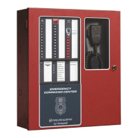
Emergency Command Center Manual — P/N LS10001-000FL-E:D 9/3/2014 5
Table of Contents
Section 1: Product Description .............................................................................................12
1.1: Product Features ..........................................................................................................................................12
1.2: Input/Output Circuit Specifications.............................................................................................................14
1.2.1: ECC-50/100 Main Control Board .....................................................................................................14
1.2.2: Display Board....................................................................................................................................18
1.2.3: ECC-CE6 Circuit Expander Module.................................................................................................19
1.3: Controls and Indicators................................................................................................................................20
1.3.1: Push-Button Controls ........................................................................................................................20
1.3.2: LED Indicators (visible with door closed) ........................................................................................21
1.3.3: LED Indicators (visible with door and dress panel open) .................................................................21
1.4: Components.................................................................................................................................................21
1.5: Optional Equipment.....................................................................................................................................23
1.6: UL 464 Low Frequency Sounders...............................................................................................................24
Section 2: Installation.............................................................................................................26
2.1: Mounting Options........................................................................................................................................26
2.2: Backbox Installation....................................................................................................................................26
Removing the Dress Panel....................................................................................................................26
Removing the Chassis Assembly .........................................................................................................27
Mounting the Backbox .........................................................................................................................28
2.3: Operating Power..........................................................................................................................................31
2.3.1: AC Power and Earth Ground Connection .........................................................................................31
2.3.2: Secondary Power Source (Batteries).................................................................................................32
2.4: Auxiliary DC Power Output Connections ...................................................................................................33
2.5: Input/Initiating Circuits ...............................................................................................................................33
2.5.1: CMD Inputs.......................................................................................................................................33
2.5.2: External Audio Input .........................................................................................................................34
2.5.3: NAC Follower Input..........................................................................................................................35
2.5.4: Night Ring .........................................................................................................................................35
2.6: Output Circuits.............................................................................................................................................36
2.6.1: Relays ................................................................................................................................................36
MNS Active Relay - TB1.....................................................................................................................36
Trouble Relay - TB2.............................................................................................................................36
AC Power Loss Relay - TB3................................................................................................................36
2.6.2: Speaker Circuits.................................................................................................................................37
2.6.3: Notification Appliance Circuit ..........................................................................................................38
2.6.4: Speaker Volume Control...................................................................................................................39
2.6.5: FACP Data Bus .................................................................................................................................40
ACS Mode Wiring................................................................................................................................41
2.7: ECC-LOC Local Operator Console.............................................................................................................42
2.8: ECC-RPU Remote Page Unit......................................................................................................................44
2.9: ECC-RM Remote Microphone....................................................................................................................46
2.10: ECC-50DA, ECC-125DA, ECC-50BDA Distributed Audio Amplifiers..................................................47
2.11: Shielding for External Device Wiring .......................................................................................................47
2.12: UL Power-limited Wiring Requirements...................................................................................................49
2.13: Installation of Option Modules..................................................................................................................50
2.13.1: ECC-CE6 Circuit Expander Module...............................................................................................50
2.13.2: Audio Amplifier Module (ECC-50W-25/70V)...............................................................................50
Installation............................................................................................................................................50
Power and Control Cables....................................................................................................................52
Configuration........................................................................................................................................52
ECC-50/100 Configurations with ECC-50W-25/70V.......
......
.............................................................53
2.13.3: 70.7 V
RMS
Transformer (ECC-XRM-70V) ....................................................................................55
2.14: Addressing External Data Bus Devices.....................................................................................................55