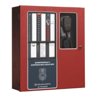
Emergency Command Center Manual — P/N LS10001-000FL-E:D 9/3/2014 19
Input/Output Circuit Specifications Product Description
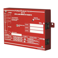
1.2.3 ECC-CE6 Circuit Expander Module
Power-limited (Class 2) circuitry
Up to six (6) circuits on the ECC-CE6 can be wired as Style Y (Class B) or Style Z (Class A).
Normal Operating Voltage for Speaker Circuits: 25 V
RMS
@ 2 amps max. and maximum Load
Impedance of 12.5
(70.0 V
RMS
@ 700 mA max. with maximum Load Impedance of 100operation possible for
the primary circuit by plugging optional ECC-XRM-70V conversion transformer into J12 of
the main control board. The same operation is possible for the optional 50W amplifier by
selecting the ECC-50W-70V model.)
Speaker circuit wiring is supervised during standby, background music, and alarm.
Output Power: 50 watts total; Frequency Range: 800 - 2,800 Hz
Maximum total capacitance: 250 µF. (Note that the total
capacitance for the speaker outputs must
not exceed the maximum of 250 µF).
End-of-Line Resistor required for Style Y (Class B) speaker circuit: 15 K, 1 watt (P/N: ELR-15K)
TB13 on the main control board: ACS/ANN (EIA-485) electrically isolated link to FACP provides
programmed speaker control