Cut along dotted line.
This sheet must be framed and mounted adjacent to the control panel.
Document LS10039-000FL-E Rev A ECN 13-186 4/9/2013
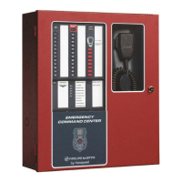
ECC-50/100 and ECC-LOC OPERATING INSTRUCTIONS
Section 1 Operating Information
NORMAL STANDBY OPERATION.
1. Green AC POWER indicator lit steadily.
2. Yellow T
ROUBLE indicators off.
3. Green speaker zone indicators off.
ALARM CONDITION.
1. Green speaker zone indicator(s) lit steadily.
2. Green S
YSTEM IN USE indicator lit steadily.
3. Audio message plays.
4. Green F
IRE SYSTEM ACTIVE indicator lit steadily (when FACP is in alarm).
5. Green MNS C
ONTROL indicator lit steadily and relay activated (for mass
notification events).
ALARM RESET. After locating and correcting a fire alarm condition at the
FACP, the system will return to Normal Standby Operation. After correcting a
mass notification event, press the MNS C
ONTROL button to clear the system
and return to Normal Standby Operation.
TROUBLE CONDITION. Activation of trouble signal under normal operation
indicates a condition that requires immediate attention. Contact your local
service representative. Silence the audible signal by pressing the T
ROUBLE
S
ILENCE switch. The trouble indicator will remain illuminated.
Section 2 Paging and Manual Message Control
1. Press the SYSTEM CONTROL button if the green LED is not lit.
2. Press either the A
LL CALL button or individual speaker zone buttons. This
will override the evacuation tone/message if panel is in alarm and activate
desired speaker circuits.
3. Once the OK TO PAGE lights green, broadcast:
•By paging: Key the microphone by pressing the push-to-talk switch on side
of microphone and speak clearly into the microphone.
•By prerecorded message: Press the desired message button.
4. Press the A
LL CALL switch (or individual speaker zone buttons) to end
broadcast and continue evacuation tone/message.
5. Press the S
YSTEM CONTROL button to relinquish control of the audio
system.
Section 3 Switch Functions
ALL CALL. Activates all speaker circuits for broadcast.
MNS CONTROL (for systems configured for mass notification operation
which has higher priority)
. Activates the MNS Active Relay and the onboard
NAC. A second press turns these back off. For a combination fire and mass
notification system, pressing MNS C
ONTROL will result in the shutdown of
audible FACP NACs and audio system speakers, allowing the system to
override the system. Pressing MNS C
ONTROL again causes the FACP to re-
activate audible FACP NACs and audio system speakers.
SYSTEM CONTROL. Manually gains control of the audio system in preparation
for an ALL CALL, message activation, or general page. The green LED will turn on
steadily to confirm control. A second press is required after paging to relinquish
control of the system. The main console will have system priority based upon user
programming. In order for the LOC to gain control, the ECC must first relinquish
control of the system.
SPEAKER SELECT 1-24. Manually activates or deactivates speaker zones
(circuits).
MESSAGE SELECT 1-8. Manually activates or deactivates stored
messages. 8th button becomes a “shift” for messages 9-14.
DIAGNOSTIC SELECT. selects a specific remote amplifier to examine
specific trouble conditions for the remote amplifiers. The fault LEDs with
wrench graphics represent the amplifier selected.
TROUBLE SILENCE. Manually silences the local trouble sounder.
CONSOLE LAMP TEST. Tests the local LEDs and sounder.
Section 4 LED Indicators
FIRE SYSTEM ACTIVE. Green LED that turns on steady when the FACP is
in alarm.
MNS CONTROL. Green LED that turns on steady when an operator has
initiated a mass notification event by pressing the MNS Control button or by
pressing an MNS message button.
SYSTEM CONTROL. Green LED that turns on steady when the main
console has control of the audio system.
SYSTEM IN USE. Green LED text that turns on steady when the main
console, an LOC, an RPU, or an RM has control of the audio system.
SPEAKER ZONES 1-24. Green LED per speaker circuit button that turns
on steady when a speaker circuit has been selected and is active. Yellow LED
per speaker circuit button that turns on steady when a speaker circuit fault
exists or when the speaker circuit has been turned off after having been
automatically turned on by the FACP.
OK TO PAGE. Green LED text that turns on steady when the system is
ready for paging.
MICROPHONE TROUBLE. Yellow LED text that turns on steady to indicate
a microphone wiring fault.
MESSAGES 1-8. Red LED per message button that turns on steady when
the message has been selected and blinks when the message has been
overridden. Yellow LED per message button that turns on steady when no
message has been recorded or there is an associated command input fault. All
eight message button LEDs will turn on steady to indicate a message generator
fault. 8th button “shift” key red off when viewing messages 1-7 and on steady
when viewing messages 8-14. Yellow LED will turn on indicating a message
trouble in the group of messages not currently being viewed.
REMOTE AMPLIFIERS 1-8 FAULT. Yellow LED per remote amplifier that
turns on steady when an amplifier has a fault.
LOC/RPU/RM 1-8 FAULT. Yellow LED per remote console that turns on
steady when a remote console has a fault. Green LED per remote console that
turns on steady when a remote console is active.
MAIN CONSOLE FAULT. Yellow LED that turns on steady when the main
(or primary operator) console has a fault.
AC POWER. Green LED that turns on steady when AC power is present.
GROUND FAULT. Yellow LED that turns on steady when a ground fault
exists in the system.
CHARGER FAULT. Yellow LED turns on steady when the battery charger
voltage is too high or low.
BATTERY FAULT. Yellow LED turns on steady when battery voltage is too
low.
DATA BUS FAULT. Yellow LED that turns on steady when the main and
remote console(s) cannot communicate.
NAC FAULT. Yellow LED that turns on steady when the onboard NAC
wiring is open or short-circuited.
NAC ACTIVE. Green LED that turns on steady when the NAC output is on.
SYSTEM TROUBLE. Yellow LED that turns on steady when any fault exists
in the system.
AUDIO RISER FAULT. Yellow LED that turns on steady when the audio
riser wiring is open or short-circuited.
Section 5 Periodic Testing and Maintenance
To ensure proper and reliable operation, system inspection and testing should
be scheduled monthly, or as required by NFPA 72 or local fire codes. A
qualified Service Representative should perform testing.
BEFORE TESTING: Notify fire department and/or central alarm receiving
station if alarm condition is transmitted. Notify facility personnel of the test so
alarm sounding devices are ignored during the test period.
AFTER TESTING: Notify all fire, central station, and/or building personnel
when testing is complete.
In the event of trouble, contact the local
Fire-Lite Service Representative.
Name: __________________________________________________
Address: ________________________________________________
Telephone Number: _______________________________________