42 Emergency Command Center Manual — P/N LS10001-000FL-E:D 9/3/2014
Installation ECC-LOC Local Operator Console
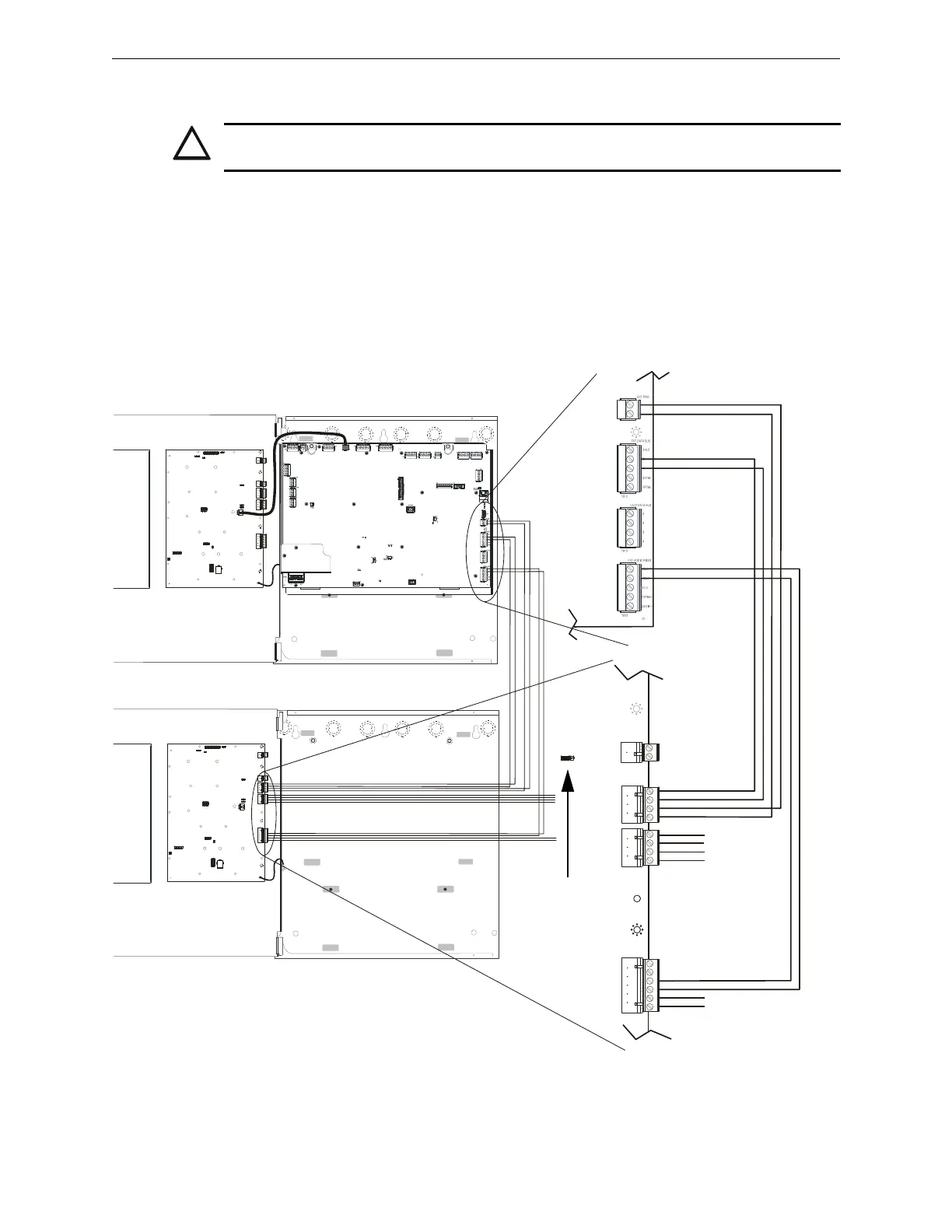
2.7 ECC-LOC Local Operator Console
Wiring for the Local Operator Console is accomplished between TB24, TB12, and TB22 on the
ECC-50/100 main control board to TB3, TB4, and TB5 on the LOC. If the ECC-LOC is the last
device on the audio and data bus chain, signal terminations are required. For the external data bus,
a removable jumper must be on pins 1 and 2 of JP2 when the LOC is the last device on the chain.
If the ECC-LOC is not the last device, the jumper must be on pins 2 and 3 of JP2 as shown below.
For the external audio riser, when the LOC is the last device, termination ELR-15K must be con-
nected to pins 5 and 6 on TB5. T-taps and multiple home runs to the main control board are not
allowed for the external data bus or the external data riser.
CAUTION: EXTERNAL WIRING CONNECTIONS
THE ECC-LOC IS A SEPARATE DEVICE, NOT PART OF THE ECC-50/100 ASSEMBLY!
J12
TB15
J9
RTZM
Rev.
ECC-MCB-PCA
ECC-50/100
main control board
ECC-LOC
display board
TB24
TB12
TB22
TB3
TB4
TB5
external operator interface
power - 24VDC
external data bus
external
audio riser
to next operator
interface or amplifier
(or, if last device,
signal termination
ELR-15K)
to next
operator
interface or
amplifier
l
o
c
w
i
r
e
b
2
.
w
m
f
Figure 2.22 Local Operator Console Wiring (Class B/Style Y)
TB2
JP2
(shown jumpered
on pins 2 and 3)