Circuits
10
411 Communicator Document #50921 Rev. E 12/09/2008 P/N 50921:E
1.3 Circuits
The 411 circuit board utilizes surface mount technology and contains a MicroController Unit (MCU), dual modular
phone line jacks, piezo sounder and two connectors for input, output and power wiring.
1.3.1 Power Requirements
Voltage for the digital communicator may be a power-limited, filtered, nonresettable nominal 12 VDC [11.2 to
12.4 VDC (UL tested range: -15%, +10%)] or nominal 24 VDC [21.3 to 24.0 VDC (UL tested range: -15%,
+10%)]. Jumper J4 is used to select the power source.
1.3.2 Channels/Inputs
Three input channels are provided on the 411 digital communicator which are used for connection to the control
panel being monitored. Each input can be programmed to monitor the control panel for:
• fire alarm activation
• trouble activation
• fire supervisory activation
• AC loss activation
Each input channel is configured as a Class B circuit and must be wired to a Normally Open contact.
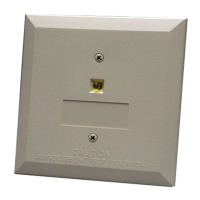
1.3.3 Primary and Secondary Phone Lines
Modular jacks are used to interface the primary and secondary phone lines to the public telephone network.
1.3.4 Earth Ground
Connect a separate earth ground wire to TB1 terminal 3 for transient protection.
Note: If zero ohms impedance exists between the 411 circuitry and earth ground, a ground fault will be indicated
at the host FACP.
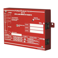
1.4 Controls and Indicator
Front Panel Switch
• Silence Switch - press to silence local 411 piezo sounder
FIGURE 1-2:411 Indicator
Comm.
Fail LED
411COVER.CDR
Piezo
Silence
Switch