Document #50907 Rev. A1 12/03/02 P/N 50907:A1
21
Input Circuits
2.4 Input Circuits
The CMP-2401B has one IDC (Initiating Device Circuit) and the CMP-2402B has two IDCs. The maximum total
loop resistance limit for each input circuit is 200 ohms. The field wiring is supervised for opens, shorts and ground
faults. All conditions are visually and audibly annunciated.
The zone(s) is a Style B (Class B) Initiating Device Circuit designed to accept any normally-open contact devices and
conventional 2-wire or 4-wire, 24 VDC smoke detectors. Resettable power is provided via TB1 Terminals 24V
Resettable (+) and Ground (-). Remove the End-of Line resistor from the FACP and install it on the IDC wiring after
the last device in the circuit. Refer to the Fire•Lite Device Compatibility Document for a list of compatible smoke
detectors.
It is allowable to mix an assortment of device types (i.e. smoke detectors, heat detectors, pull stations, etc.) on the
same zone.
TB1
TB2
REMOTE
GND AC TBL BUZ
++++
---
NC NCCCNO NO
ALARM
TROUBLE+24 VDC
RESET
SIGNAL
OUTPUT
INITIATING
ZONE 1
INITIATING
ZONE 2
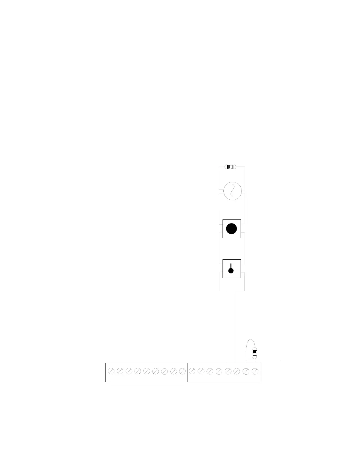
FIGURE 2-5:
CMP-2402B Style B Initiating Device Circuit Connections
UL listed compatible 2-wire smoke detector
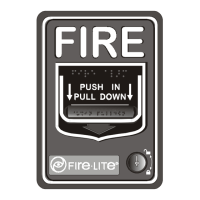
Manual Pull Station
Heat Detector
Dummy load unused circuit
Style B (Class B) Initiating Device Circuit (supervised
and power-limited).
3.9K ohm, ½ watt
2402IDC.CDR