Installation of Optional Module
24
Document #50907 Rev.A1 12/03/02 P/N 50907:A1
2.7 Installation of Optional Module
CAUTION: Remove all power (AC and DC) before installing or removing modules or wiring.
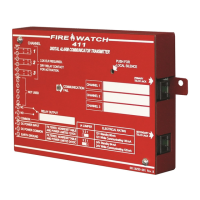
2.7.1 4XTMF Transmitter Module
Push the disconnect switch to the down position to prevent accidental activation of the municipal box during
testing of the control panel. The Disconnect LED will remain illuminated while the municipal box is
disconnected. The System Trouble LED will indicate disconnected and/or open circuit conditions on the
municipal box. During trouble conditions, it is possible to obtain the circuit condition on the alarm reverse
polarity output. If this operation is desired, cut the TBL jumper on the 4XTMF module.
J1
J4
TROUBLE SIGNAL
OUTPUT
CUT IF 4X
OPTION
BOARD IS
PRE SENT
CUT TO
DISABLE
EARTH
FAULT
INITIAT
ZONE 1
INITIAT
ZONE 2
J3
BATTERY
TBL SILENCE
SIG SI LENCE
ZONE 1
SIG SI LENCE
ZONE 2
SY ST EM RES ET
NC C
-
-
-
+
+
+
NO
TB2
R72
R14
SW4
SW2
SW1
SW3
FIGURE 2-10:
4XTMF Module Connections
4XTMF Module
Install 4XTMF Module by
plugging into connector
J6
and
J7
on CMP-2401B/02B main
board
TBL Jumper
Cut R14 for 4XTMF module
placement supervision
1 (+)
2 (-)
3 (+)
4 (-)
5
6 (+)
7 (-)
Remote Alarm (power-limited)*
Remote Trouble (power-limited)*
Municipal Box (nonpower-limited)*
no connection
* Wiring from these terminals can
exit the protected premises.
Disconnect Switch
Disconnect LED
Polarities are shown for
module activation
4XTMF.CDR
2402BRD2.CDR