Programming Options
26
Document #50907 Rev.A1 12/03/02 P/N 50907:A1
CHAPTER 3 Programming Options
This chapter describes the programming options available by cutting resistors on the FACP main circuit board.
Options should be selected (resistors cut if necessary) prior to applying power to the control panel.
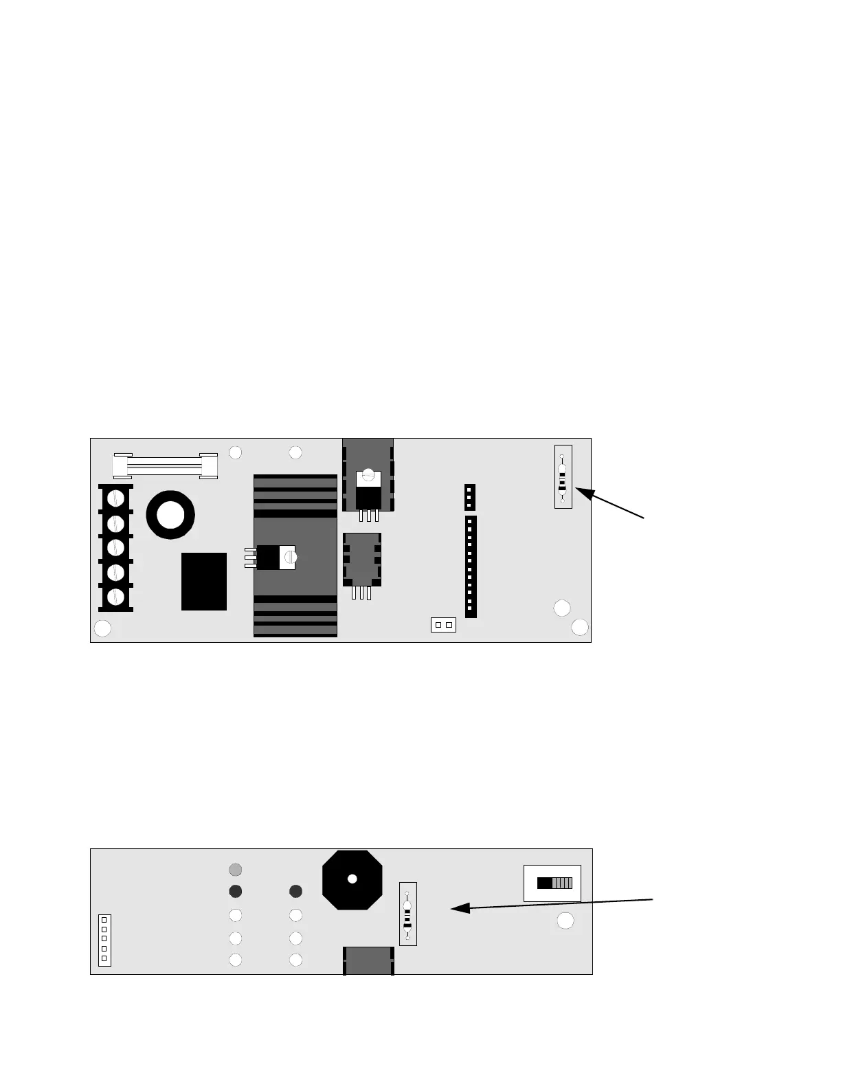
3.1 Earth Ground Fault Detection
The FACP is factory configured to automatically detect ground fault conditions. A ground fault occurs when a low
resistance is detected between an FACP circuit and earth ground. This condition will cause the System Trouble LED
and Ground Fault LED to turn on and the piezo sounder to pulse.
The Ground Fault Detection circuit can be disabled by cutting resistor R72 on the main circuit board. Refer to the
local codes and consult the local Authority Having Jurisdiction before disabling the Ground Fault Detection circuit.
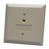
3.2 Optional 4XTMF Transmitter Module Placement Supervision
The 4XTMF module can be used to connect the FACP to a City Box or Reverse Polarity Remote Station. To super-
vise placement and operation of the module, cut resistor R14. Refer to the local codes and consult the local Authority
Having Jurisdiction before installing the 4XTMF Transmitter Module.
J1
J4
TB3
NEUTRAL
EARTH HOT
CUT TO
DISABLE
EARTH
FAULT
J3
BAT TERY
R72
FIGURE 3-1:
Ground Fault Detection Circuit
R72
Cut to Disable Ground
Fault Detection
2402BRD3.CDR
J5
CUT IF 4X
OPTION
BOARD IS
PRESENT
TBL SILE NCE
R14
SW4
FIGURE 3-2:
4XTMF Module Placement Supervision
R14
Cut to Supervise Placement
of 4XTMF Module when
installed
2402BRD4.CDR