EQUIPMENT: DUO-CEL WRITTEN BY: RKP
PUBLICATION: OM_DUO-CEL_INST CHECKED BY: AJC
ISSUE No. & DATE: 2 13/10/10
PAGE 28 of 30
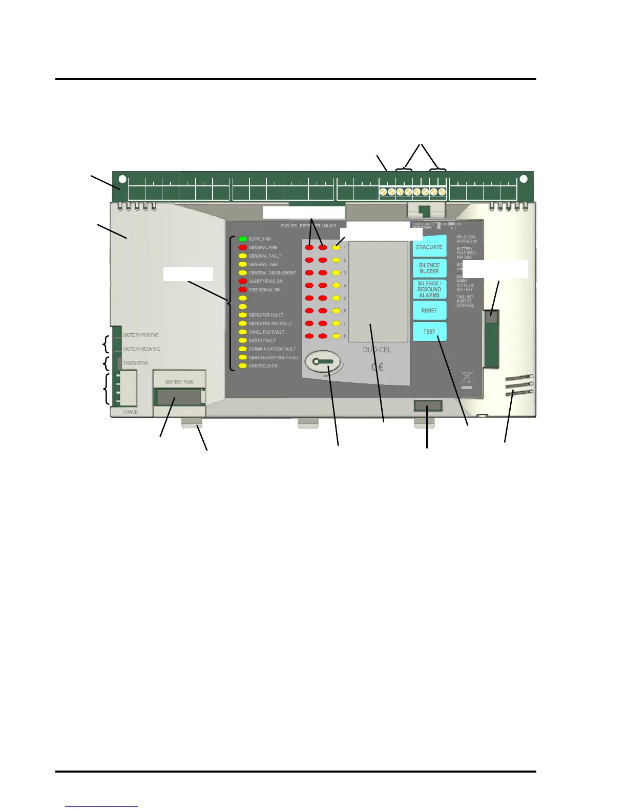
Figure 14 illustrates the control board for the DUO-CEL repeater with the PCB cover fitted.
ZONE 1
Z1 + Z1 –
ZONE 2
Z2+ Z2 –
ZONE 3
Z3+ Z3 –
ZONE 4
Z4+ Z4 –
ZONE 5
Z5+ Z5 –
ZONE 6
Z6+ Z6 –
ZONE 7
Z7+ Z7 –
ZONE 8
Z8+ Z8 –
FIRE SIGNAL
+ –
FIRE RELAY
N/O P N/C
FAULT RELAY
N/O P N/C
REMOTE
I/P 0V DIS. EVAC. BUZ.
AUX 0.25A
24V 0V
REPEATER
A B BA0V24V
ALARM CIRCUITS
AL1+ AL1 – AL2+ AL2 – AL3+ AL3 – AL4+ AL4 –
24VDC
INPUT
For DC
powered
repeater
RS485
COMMS.
TERMINALS
BATTERY
LEADS
THERMISTOR
LEAD
POWER
SUPPLY
LEAD
BATTERY
FUSE
GENERAL LED
INDICATORS
ACCESS KEY
ENTRY
USER
CONTROLS
INTERNAL
BUZZER
CONFIGURATION
DIL SWITCHES
MICROCONTROLLER
PROGRAMMING
SOCKET
ZONAL FIRE LEDs
ZONAL FAULT LEDs
MOUNTING
TAB
PCB
COVER
PCB
REMOTE O/PS
NOTE:
24V & 0V Terminals are only
available on the DC powered
repeater panel.
NOTE:
Power Supply
connections and
battery fuse are only
on the mains
powered repeater.
ZONE
LOCATION
INSERT
SOUNDER FLT / DIS / TST
FIRE SIGNAL FLT / DIS / TST
Figure 14 – Repeater control board and PCB cover
Note:
The Microcontroller programming socket is for use during manufacturing only and should not have any links
fitted across any of the pins. Improper use of the connector may result in permanent damage to the control
board.