EQUIPMENT: DUO-CEL WRITTEN BY: RKP
PUBLICATION: OM_DUO-CEL_INST CHECKED BY: AJC
ISSUE No. & DATE: 2 13/10/10
PAGE 23 of 30
After a few seconds, the Communication Fault
at the third repeater should clear and the panel
& repeaters should be in the quiescent state.
If the panel or any repeater shows a fault then
trace and clear the fault before proceeding.
8.6.1 Repeater Testing
Repeat the following tests at each repeater to
ensure each repeater is working correctly.
1. With the ACCESS key removed press the
TEST button and check that all LEDs
illuminate and the buzzer sounds.
2. Turn the Access key to the vertical position
and press the EVACUATE button. Check that
all sounders operate. At each repeater, check
that the ALERT/EVAC ON LED illuminates
and the internal buzzer operates.
3. Press the SILENCE BUZZER button on the
repeater. Check that the internal buzzer
silences on all repeaters.
4. Press the SILENCE ALARMS button on the
repeater. Check that the sounders silence.
5. Operate a Manual Call Point or detector on
each zone in turn. Check that all repeaters
indicate the alarm.
6. Reset the MCPs and press the RESET button
on the repeater. Check that the panel and
repeaters return to the quiescent state.
7. Set the first repeater address to 0. Check that
the panel illuminates the REPEATER FAULT
& FLT REP 1 LEDs. Check that any additional
repeaters display a steady
COMMUNICATION FAULT LED.
8. Set the first repeater address back to 1 and
check that the panel and repeaters return to
normal.
9. Set the second repeater address to 0. Check
that the panel illuminates the REPEATER
FAULT & FLT REP 2 LEDs. Check that any
additional repeaters display a steady
COMMUNICATION FAULT LED.
10. Set the second repeater address back to 2 and
check that the panel and repeaters return to
normal.
11. Set the third repeater address to 0. Check that
the panel illuminates the REPEATER FAULT
& FLT REP 3 LEDs. Check that any additional
repeaters display a steady
COMMUNICATION FAULT LED.
12. Set the third repeater address back to 3 and
check that the panel and repeaters return to
normal.
8.7 Power Supply Unit.
1. Ensure that the system is fully commissioned
with all output circuits loaded as required by
the system design.
2. Ensure that the batteries have been on charge
for at least 2 hours.
3. Isolate the primary power supply feed to the
panel.
4. Check the panel and repeaters indicate power
supply fault.
5. Operate the EVACUATE button to load the
panel.
6. Confirm that the system continues to function
correctly.
7. Press the SILENCE ALARMS button and
restore the primary supply. Check that the
panel & repeaters return to the quiescent state.
Repeat the above steps for any mains powered
repeaters.
8.8 Final Dressing of the Cables
Ensure that the field conductors are secure and tidy
inside the enclosure. Check that all cables are
firmly held in the terminal blocks & Earth bar.
Check that the Earth Bar is firmly fixed to the
enclosure. Check that all Earth leads are correctly &
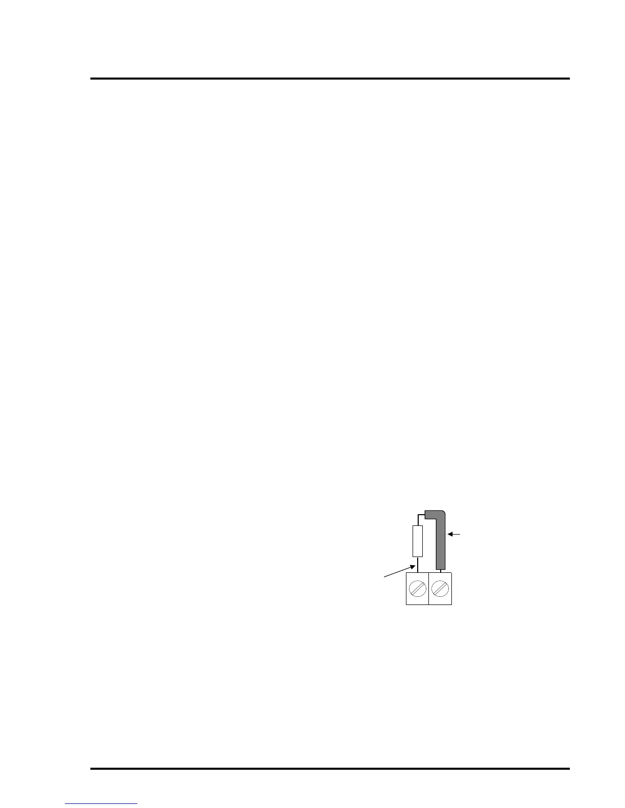
firmly connected. Check that End-Of-Line devices
in unused circuits are positioned in a safe manner
and are unlikely to create short circuit faults due to
movement. It is advised that unused EOL devices
have insulating sleeving placed on the leads for
safety.