EQUIPMENT: DUO-CEL WRITTEN BY: RKP
PUBLICATION: OM_DUO-CEL_INST CHECKED BY: AJC
ISSUE No. & DATE: 2 13/10/10
PAGE 12 of 30
5.1 Pre-installation Checks
1. Carefully remove the control panel from the
packing and lay the panel on a suitable flat
surface.
2. Undo the three screws holding the front cover
to the back box (one at the top, two at the
bottom).
3. Remove the front cover and return it to the
packing box.
4. Locate the spares bag and check that the
following items are present.
a. Set of battery leads (1 each of Red, Black
& Blue)
b. Plastic keys for control panel control
access (2-off).
c. Up to 8 10uF capacitors (or composite
zone EOL devices for twin-wire panels)
for zone EOL dependant on number of
zones. These may already be fitted in the
panel terminals.
d. Up to 6 10K resistors (1 for Fire Signal
output EOL, 1 for Remote Input EOL, 4
for Alarm EOL dependant on number of
alarm circuits)
e. 1 each of 2K2, 220R, 1K, 4K7 and 470R
resistors for the Remote Input Switches.
f. 1 Terminal cover-plate for the power
supply unit.
g. 1 Cable Tie for holding the mains cable
h. 1 blank insert for zone text
i. 1 Battery Fuse, 2A fast blow 20mm glass.
j. 1 Battery clamp (may already be fitted in
panel)
All items, except for the battery fuse, will be
required for the installation of the panel.
5.1.1 DUO-CEL Panel Installation
Instructions
The front cover should have been removed as
detailed above in the pre-installation checks. The
front cover is not required during installation and
commissioning, so leave it safely stored in the
original packing box.
1. Remove the control board complete with
cover as follows:
a. Disconnect the two power leads at the
left-hand side of the control board.
b. Undo the two screws at the top of the
control board and remove the control
board complete with the cover. Place the
control board & cover inside the original
packing box for safety.
c. The two screws can be re-inserted into
the threaded bushes for convenience.
The power supply should not be removed.
2. Identify the indented holes in the back of the
enclosure that are used to mount the
enclosure.
3. Determine the best location for the enclosure.
This should be dust & moisture free, not
subject to mechanical vibration or shock. The
panel should be mounted at least 2 metres
away from any radio transmitting equipment
such as pager systems and other wireless
equipment.
4. Position the enclosure against the wall and
mark the location of the keyhole at the top-
centre on the back box.
5. Drill and loosely fix the enclosure using
suitable fixings (not supplied).
6. Level the enclosure and mark the four fixing
holes at each corner of the back box.
7. Drill and firmly fix the enclosure to the wall.
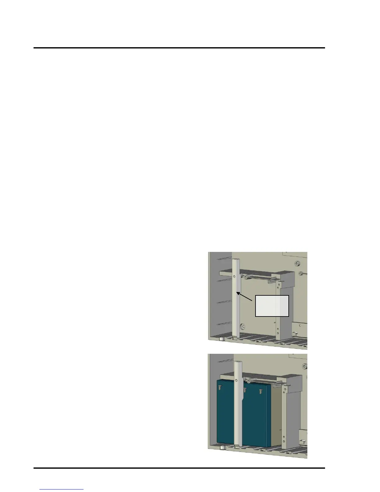
8. Remove the battery clamp which is held in
by one screw (if fitted).