EQUIPMENT: DUO-CEL WRITTEN BY: RKP
PUBLICATION: OM_DUO-CEL_INST CHECKED BY: AJC
ISSUE No. & DATE: 2 13/10/10
PAGE 9 of 30
Figure 10 – Remote Indicators Wiring Diagram
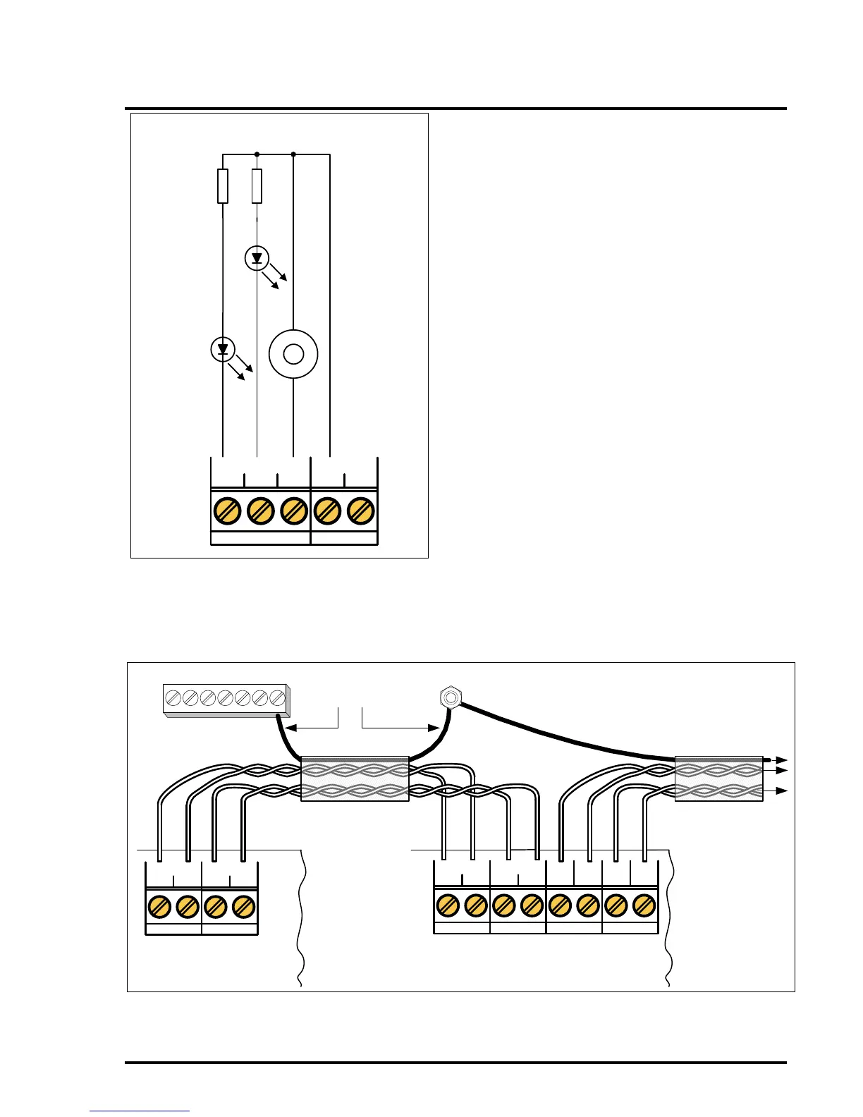
3.9 Panel to Repeater Wiring
The Repeater RS485 communication and 24Vdc
power connections should all be made via a single
multi-core data cable. The number of cores required
is two if the repeater is mains powered, or four if
powered from the panel. A cable screen is not
required but is usually present in most data cable
types. The A & B lines should be connected via one
set of twisted pair cores, the 24V & 0V lines should
be connected via another set of twisted pair cores.
If the cable includes a screen then this should be
earthed at the panel & all repeaters.
Terminal A at the panel must be connected to
Terminal A at all repeaters, Terminal B at the panel
must be connected to Terminal B at all repeaters.