EQUIPMENT: FIRECLASS DUO -CEL WRITTEN BY: RKP
PUBLICATION: OM_FC_DUO-CEL_INST CHECKED BY: AP
ISSUE No. & DATE: 0 01/03/12
PAGE 13 of 29
NOTE: Only use the battery leads
supplied, with insulated connectors.
12. Fix the control board (with PCB cover) back
into the enclosure, bringing the leads from
the power supply unit underneath the control
board and over the right-hand battery.
Ensure that the earth lead is correctly
attached to the control board by the left-hand
screw.
Connect the leads to the Sounder Expansion
board if fitted.
13. Connect the power supply leads to the
control board.
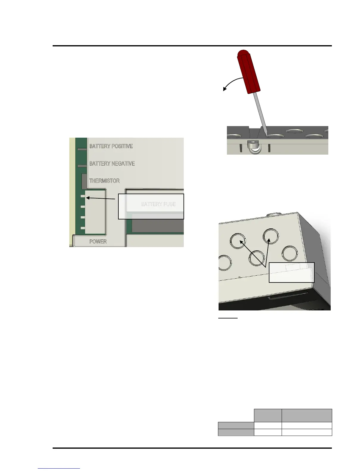
14. Connect the black battery lead to the
BATTERY NEGATIVE spade terminal on the
control board.
15. Determine the number of cable entry holes
required and remove the necessary
knockouts from the top of the enclosure.
These knockouts can be removed by
inserting a flat-bladed screwdriver into the
slot on the rim of the knockout and gently
levering the knockout out.
WARNING: The knockouts are designed
to be removed with ease. Excessive force
may damage the enclosure.
NOTE: The knockout cannot be re-
inserted once removed.
16. Gland the wring into the enclosure using
20mm cable glands. Do not connect the
cables to the control panel at this stage.
The Mains cable should be glanded via one
of the cable-entries shown below:
NOTES
An appropriate lockable double pole
disconnect device shall be provided as
part of the building installation. This must
be labelled ‘FIRE ALARM. DO NOT
SWITCH OFF’. This device must have a
minimum contact gap of 3mm.
The mains supply must be via a dedicated
circuit exclusive to the panel. The mains
supply to the panel must be protected by
a 5A fuse.
Use only mains cable compliant to
BS6004, BS6500, or equivalent, within the
following limits: