ENGLISH
Important Notes
The FC501-L, FC501-H and FC501-HK models sup
-
ports 3 loops of 128 addresses or 128 addresses in one
Loop only. Loop lengths are to be a maximum of 2 Km
(Dependant on device types, quantities connected &
cable type).
A maximum of 4 FC500REP repeaters, and 4
FC500MFI modules can be driven from a FC501 ad
-
dressable panel. The Loop devices can be addressed
and configured from the panel menu (this is explained
later within this document, " Autoaddressing Procedu
-
re").
in alternative the FC490ST service tool can be used to
address your field devices.
!
WARNING: Please read this section completely
before commencing installation.
The control panel must be installed by competent engi
-
neers familiar with the installation of fire detection
systems. In addition, it is recommended to refer to the
following information:
Ø
Current edition of the local laws about wiring regu
-
lations.
Ø
Fire detection and alarm systems in buildings or the
installation standards for the relevant country.
Ø
Any specific site requirements.
Ø
FireClass field device installation instructions.
ENGLISH 13
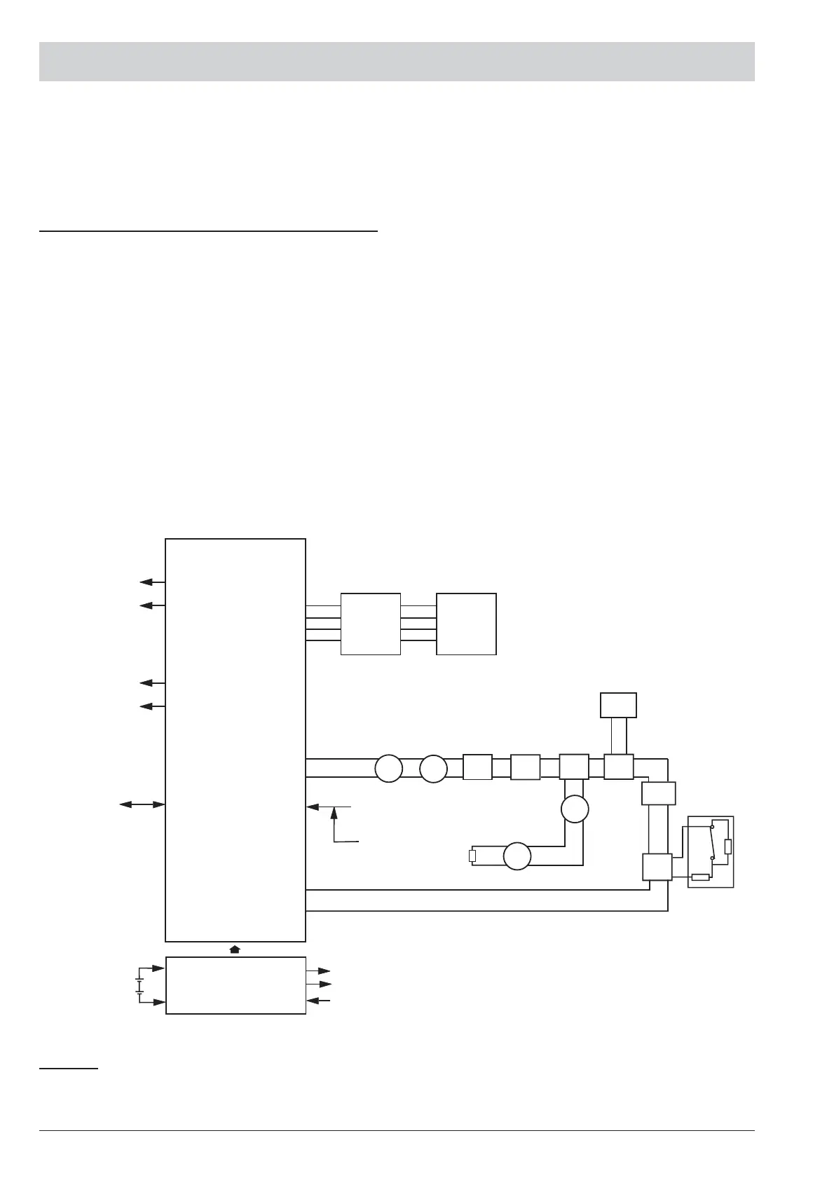
CONTROLLER
ALARM RELAY
FAULT RELAY
BAQ35T24/
BAQ60T24
AUX 24V
OUT
230VAC
NOTE: Fire alarm cables should be segregated from all other (non-fire alarm) cables.
24V
BATTERY
SOUNDER CIRCUIT 1
SOUNDER CIRCUIT 2
CONFIGURATION
UPLOAD/DOWNLOAD
PC-LINK
PORT
ADDRESSABLE
CIRCUIT
PLANT
(*) CONVENTIONAL
DETECTORS
DET*
EOL
DET*
DET DET
IB
WHITH
DET
FC500IP
CP
DIM
RIM
LI
CIM
EO
CONTACT
+LEFT–
–RIGHT+
24V – +
M
Rs485
REPEATER
FC500REP
REMOTE
BUS
CONFIGURATION
UPLOAD/DOWNLOAD
USB
DET- ADDRESSABLE DETECTOR
DET*- CONVENTIONAL DETECTOR
IB-ISOLATORBASE
CP- CALL POINT
DIM- DETECTOR INPUT MODULE
RIM- RELAY INTERFACE MODULE
CIM- CONTACT INPUT MODULE
LI- LINE ISOLATOR
KEY
FC500MFI
Figure 5 A schematic diagram for a typical system layout