MANUAL for the basic control panel | CCB2.0
Description, Function and Article Code
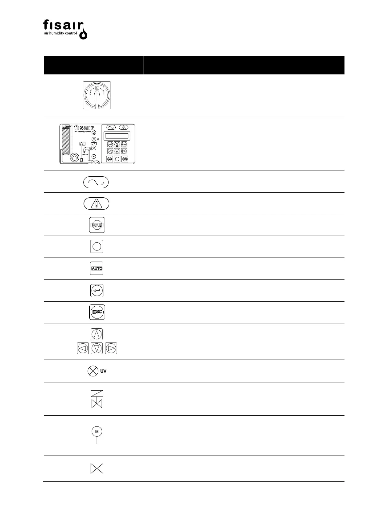
Disconnector switch (I1) for cutting and isolating the
supply voltage; possibility of locking by padlock (not
supplied)
Art. Cod.: 64300129
HMI. Command and display interface SEF-027.1
Art. Cod.: 52300012
LED. Yellow. Live equipment
Operating key in Manual mode
Start/stop status change button
Operating key in Automatic mode.
LED. Blue. UV Lamp is operating
LED. Yellow. Indicates the water supply solenoid valve
is powered
LED. Green. Indicates the drain valve motor is
powered
LED. Green. Indicates the drain motor valve is open
(requires feedback connection)