14
4. Electrical Installation
All wiring connections should be made with good quality shielded instrument cable; wiring
between terminals which are inside the instrument enclosure, or between a flowmeter and an
integrally mounted instrument may use non-shielded wire. Cable shields or drain wires should
be connected to the instrument ground (GND) at the instrument end only – isolate the
shield/drain wire at the flowmeter end of the cable.
The terminal connections on the instrument will allow for usage of wiring up to 1.5mm
2
cross
section (16AWG). Wire insulation should be stripped to a length of 7mm and conductors
should be fitted to the terminals so that there is minimal exposed conductor. Terminals can be
tightened with a 2.5mm flat blade screw driver.
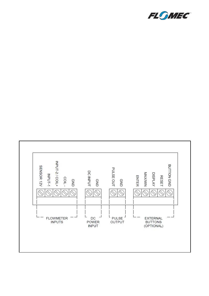
4.1 Terminal Identification
The terminal connections are divided into 4 separate sections by their function, see image
below. There is a separate ground (GND) terminal in each section of terminals; as this
instrument has a common ground, all GND terminals are internally connected.