10. Using a
5
16
in. open-end wrench, remove the inlet
screw from the face of the check valve body.
Remove the inlet check valve support and the inlet
poppet.
11. Clamp the check valve assembly in the soft-jawed
vise, holding the assembly on the flats of the check
valve body.
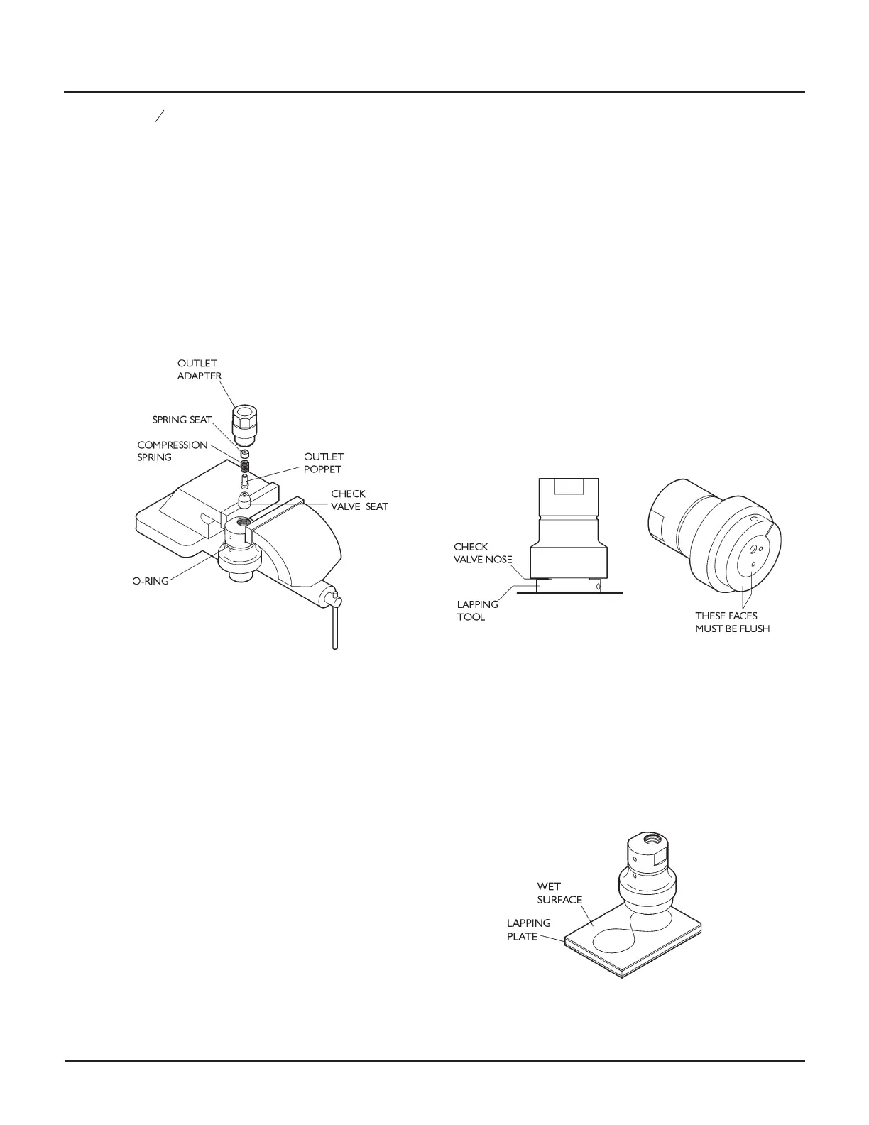
Remove the outlet adapter (loosened in an earlier
step) from the check valve body. Remove the out
-
let check valve poppet, compression spring, check
valve seat, and outlet spring seat and set aside.
Also remove the large o-ring from the check valve
body and set it aside.
12. Clean and inspect the check valve body and outlet
adapter.
Lapping the check valve body
Lapping notes
•
The dimensions for the check valve body listed at the
beginning of Maintenance Procedure D are the mini
-
mum allowed. You can re-use the check valve body
down to these dimensions, but you must discard the
check valve body if it becomes smaller.
•
Hand lapping, machining, machine grinding, polishing,
or a combination thereof are usually all acceptable
ways to remove surface imperfections from compo
-
nents before final lapping.
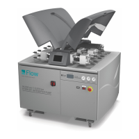
13. Install the check valve body lapping tool (014853-1)
around the check valve nose. Place the assembly, end
face down, on a flat surface. Slide the tool down as far
as it will go, until the check valve body and tool end
faces are flush. Tighten the lapping tool onto the check
valve body.
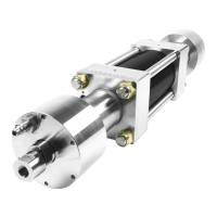
14. Attach a 320 grit abrasive strip to one side of the glass
plate, and a 600 grit strip to the other side.
Place a few drops of water on the 320 grit side of the
lapping plate. Lap the check valve body in a figure-8
pattern until all surface imperfections have been
removed.
© Flow International Corporation M-376 | 39
CHAPTER 3
Maintenance Procedures