31. Continue sliding the piston into the cylinder until the
empty seal groove on the piston exits the other end
of the cylinder.
CAUTION
If the seal starts to come out of the end of the cylinder,
do not force it back against the flare. Instead, push
the whole piston assembly through and start again,
this time stopping before the seal appears.
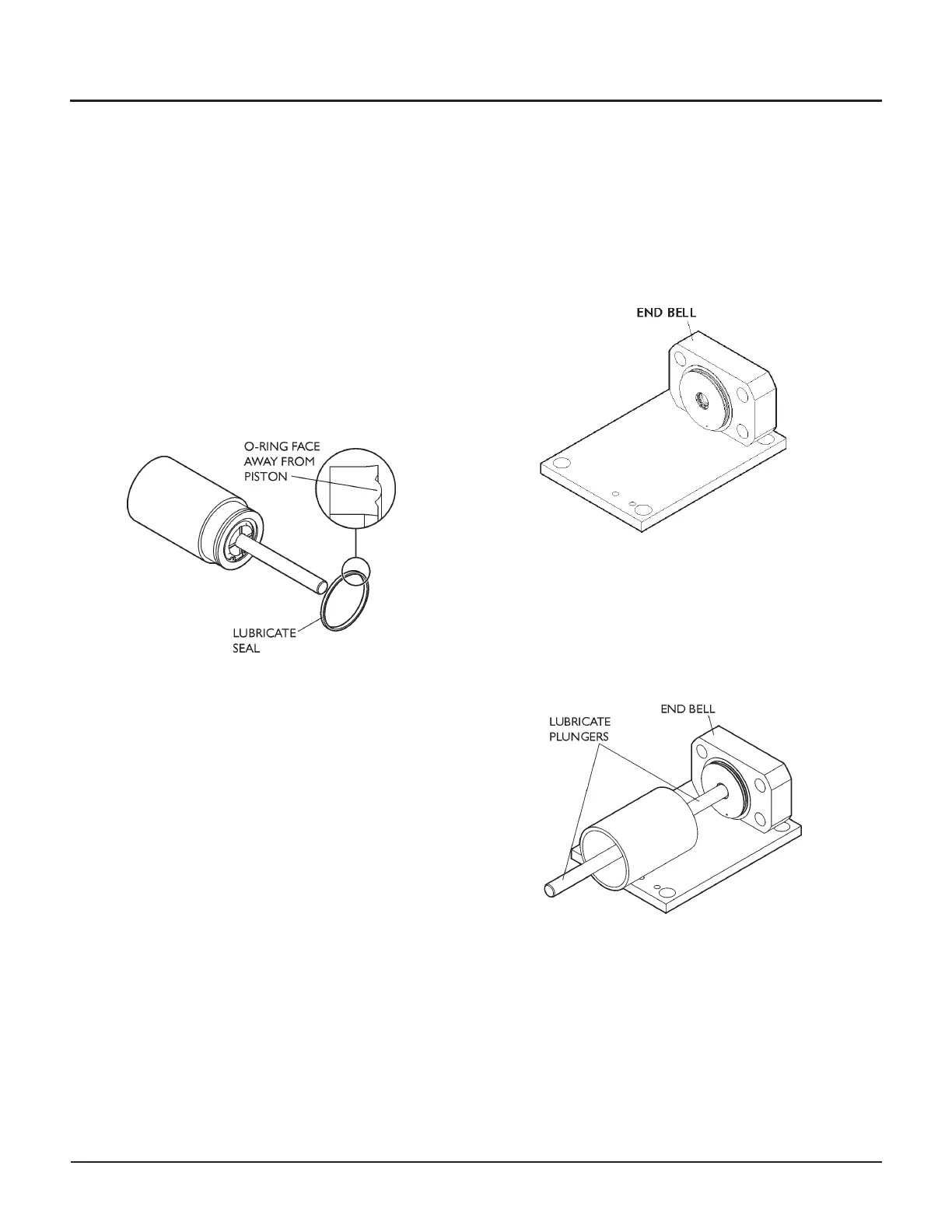
32. Apply clean hydraulic oil or Parker Super O-Ring to
the seal and install it in the groove on the piston,
making sure the flared o-ring face is toward the out
-
side of the piston.
33. Slide the piston and plunger back into the cylinder.
Take care when the seal is being compressed as it en
-
ters the cylinder—the seal can easily be damaged by
rough handling at this point.
Note: Centering the piston will make intensifier
re-assembly easier.
Set the cylinder containing the piston and plunger as
-
sembly aside.
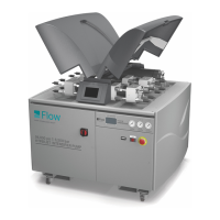
34. Mount an end bell to the assembly fixture. Insert the
fixture plate screw(s) and fasten finger tight.
Notes:
•
The short-block intensifier has one fixture plate
screw; the long-block intensifier has two
screws.
•
The backup ring and o-ring were lubricated
andinstalledinStep21.
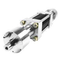
35. Apply clean hydraulic oil or Parker Super O-Ring
Lube to both plungers. Install the cylinder by insert-
ing the plunger into the end bell.
36. Slide the remaining end bell over the other plunger
and seat it on the assembly fixture.
56 | M-376 © Flow International Corporation
94K HYPERPRESSURE INTENSIFIER