EasyManuals Logo

Flowserve DMX User Manual

Flowserve DMX
26 pages
To Next Page IconTo Next Page
To Previous Page IconTo Previous Page
Page #21 background imageLoading...
Page #21 background image
DMX/DMXD/DMXH/DMXD
H
USER
INSTRUCTIONS
ENGLISH
71569282
-
10/09
Page 38 of 60
In case of double suction pump (DMXD and
DMXDH), remove crossover bushing [1600].
Crossover bushing is horizontally split and held
together by dowel pins [6810].
e)
Remove
channel
rings
[1500]
from
impeller
back
ring at each impeller. Channel rings are
horizontally split and are held together by
shoulder screws or dowel pins.
Channel rings are precision machined as a
set, after being dowelled. They should be match
marked and numbered for reassembly purposes. It is
suggested that the two halves be placed back
together immediately.
f)
Remove
center
bushing
[1600]
from
center
(back
to back) impellers. Center bushing is horizontally
split and held together by socket head cap-
screws [6570] and dowel pins [6810].
6.6.7
Dismantling
the
rotor
a)
Remove
throttling
sleeve
[2430].The
throttling
sleeve has a shrunk fit to the shaft and will have
to be heated to remove. Heat throttling sleeves
O.D. evenly throughout its length to
approxi
mate
ly 1
49 °
C (3
00 °
F) us
ing a
torc
h wit
h
a fine tip.
Push
throttling
sleeve
inboard
(towards
impeller)
Remove
split
ring
[2531]
Throttling
sleeve
can
now
be
removed
from
end of shaft
Remove
throttling
sleeve
key
[6700]
b)
Heat
(per procedure
in 6
.6.8) and
remove the
first
outboard impeller [2200], split ring [2531] and
impeller key [6700].
When heating parts, gloves or other suitable
protection must be worn.
After impeller is heated, it will have to be pushed
towards the center of the pump, the split rings [2531]
removed and quickly pulled from the end of the shaft.
The shaft is step machined at each impeller
fit to ease the disassembly process. It is
recommended that each impeller be marked with
stage number to insure proper reassembly.
6.6.8
Heating
impellers
for
removal
a)
Apply
heat (torch
with fine
tip) to
periphery [outer
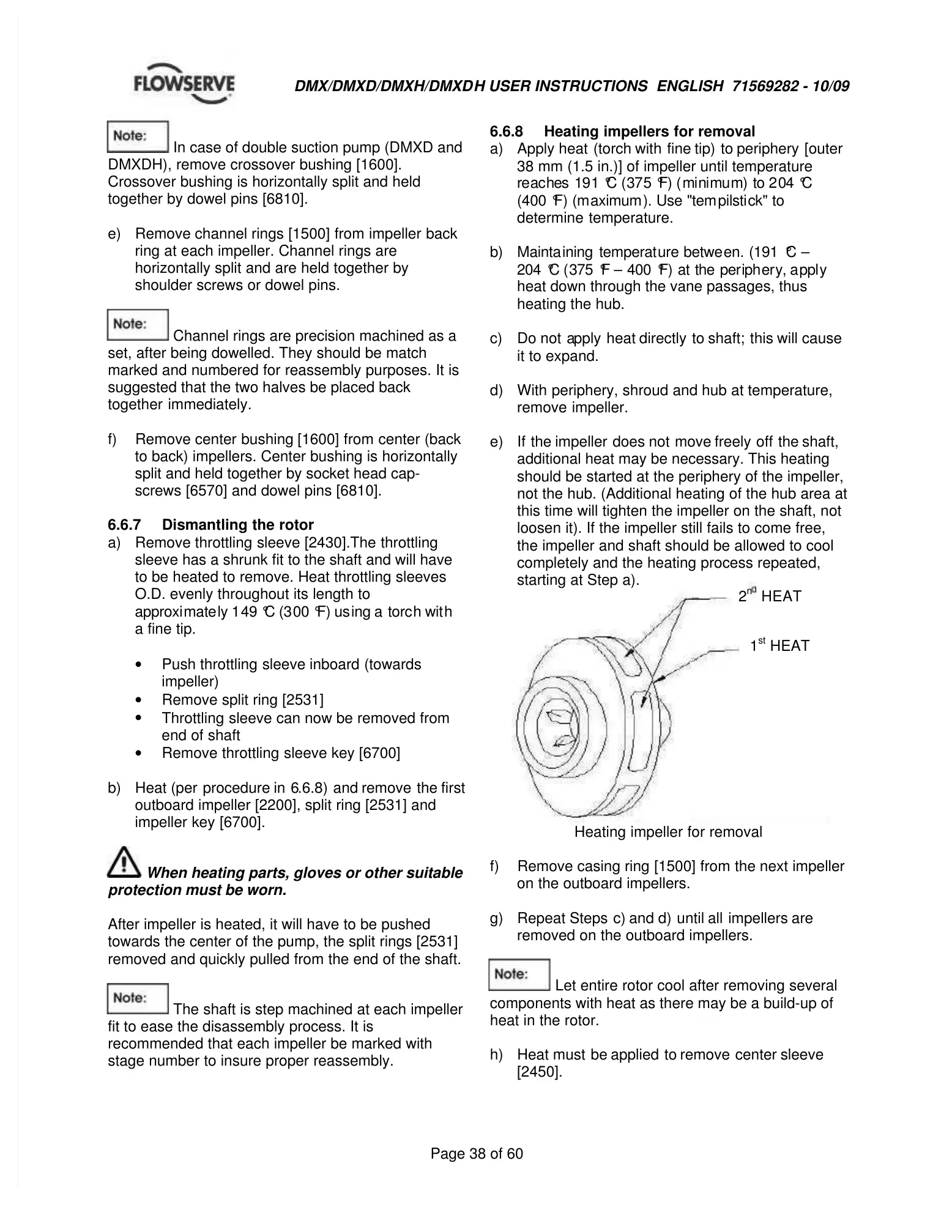
38 mm (1.5 in.)] of impeller until temperature
re
ac
hes
19
1 °
C (
37
5 °
F) (
mi
ni
mu
m)
to 2
04 °
C
(400 °
F) (m
aximum
). Use "tem
pilsti
ck" to
determine temperature.
b)
Mainta
ining temperat
ure
betwe
en.
(191 °
C
204
°
C (
375
°
F
400
°
F)
at
the
per
iph
er
y, a
ppl
y
heat down through the vane passages, thus
heating the hub.
c)
Do
not a
pply heat
directly to
shaft; this
will
cause
it to expand.
d)
With
periphery,
shroud
and
hub
at
temperature,
remove impeller.
e)
If the
impeller does
not move
freely off the
shaft,
additional heat may be necessary. This heating
should be started at the periphery of the impeller,
not the hub. (Additional heating of the hub area at
this time will tighten the impeller on the shaft, not
loosen it). If the impeller still fails to come free,
the impeller and shaft should be allowed to cool
completely and the heating process repeated,
starting at Step a).
Heating impeller for removal
f)
Remove
casing
ring
[1500]
from
the
next
impeller
on the outboard impellers.
g)
Repeat
Steps c)
and
d) until
all impellers
are
removed on the outboard impellers.
Let entire rotor cool after removing several
components with heat as there may be a build-up of
heat in the rotor.
h)
Heat
must be
applied to
remove center
sleeve
[2450].
2
n
HEAT
1
st
HEAT

Questions and Answers:

Question and Answer IconNeed help?

Do you have a question about the Flowserve DMX and is the answer not in the manual?

Flowserve DMX Specifications

General IconGeneral
BrandFlowserve
ModelDMX
CategoryWater Pump
LanguageEnglish

Related product manuals