Limitorque L120-85 Installation, Operation and Maintenance FCD LMENIM1202-03-A4 – 06/15
12
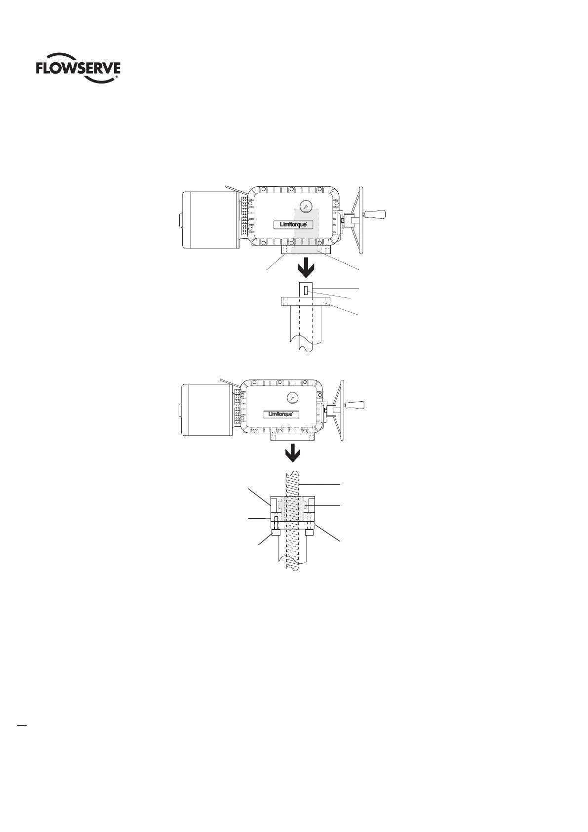
B. Torque and Thrust Applications (Drive 2)
Screw the Thrust Base Assembly onto the Threaded Valve Stem and secure the Thrust Base Assembly to the Actuator Mounting
Base using Socket Head Cap Screws (piece 110) and Lockwashers (piece 111).
Figure 4: L120-85 Torque Drive Nut orientation (Drive 1)
Drive 1
Actuator
Mounting
Base
Actuator
Mounting
Adapter
Valve
Stem
#95 Torque
Drive Nut
Key
Note: Key is shown for reference.
It may be in one of several other
orientations in reference to the
actuator.
Figure 5: L120-85 Thrust Base Assembly orientation (Drive 2)
Drive 2 Actuator
Mounting Base
Actuator
Mounting
Adapter
Threaded
Valve Stem
#101 Thrust Base
(Drive Sleeve)
Thrust Base
Assembly
#110 Socket Head
Cap Screws
#111 Lockwashers
4.2 Verifying Motor Rotation Direction
4.2.1 Initial Electrical Connections
c
WARNING: Hazardous Voltage. No electrical power should be connected until all wiring and Limit Switch adjustments have been
completed. Once power is supplied to actuator, exercise caution if cover is not installed.