37
Limitorque L120-85 Installation, Operation and Maintenance FCD LMENIM1202-03-A4 – 06/15
flowserve.com
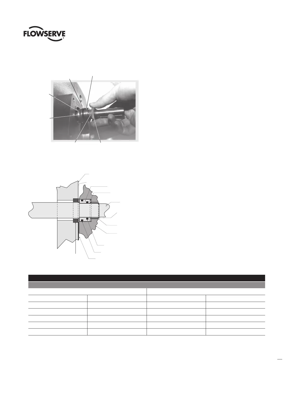
Figure 21: Shimming parts and their order of assembly
#6-1 & 6-2
Shims
#6-1 & 6-2 Remaining Shims
#4-1 Handwheel
Bushing
#43 O-ring
(not shown)
#4-2 Handwheel
Spacer
#52 Handwheel
Shaft
Washer
Figure 22: Shim location for gap “B” dimension
#5 Handwheel
End Cap
#42-4 Gasket
#4-1 Handwheel Bushing
#1 Housing face
(Handwheel end of actuator)
#4-2 Handwheel
Spacer
#Shims for
gap "B"
Shims for gap "A"
#4-3 Retaining Ring
#44 O-Ring
#43 O-Ring
#52 Handwheel
Shaft Washer
Table 5: Gap “B” shim thickness selection chart
Shim Thickness for Gap “B”
Shim Thickness
Used at gap “A” Required for gap “B”
.03" 0.76 mm .15" 3.81 mm
.06" 1.52 mm .12" 3.05 mm
.09" 2.29 mm .09" 2.29 mm
.12" 3.05 mm .06" 1.52 mm
.15" 3.81 mm .03" 0.76 mm
.18" 4.57 mm 0" 0 mm
10. Install Gasket (piece 42-4) and Handwheel End Cap (piece 5). Secure these pieces with four Hex Head Cap Screws (piece 50-3) and
Lockwashers (piece 50-4). Handwheel Shaft end play can be examined but is not required. According to dimensional tolerances, the
Handwheel end play with proper shimming techniques will be .000 to .034 inches (.00 mm to 0.86 mm).
11. When reassembling the thrust base, ensure EP-0 lithium base lubricant is replaced.