15
Limitorque L120-85 Installation, Operation and Maintenance FCD LMENIM1202-03-A4 – 06/15
flowserve.com
4.3 Limit Switch Settings
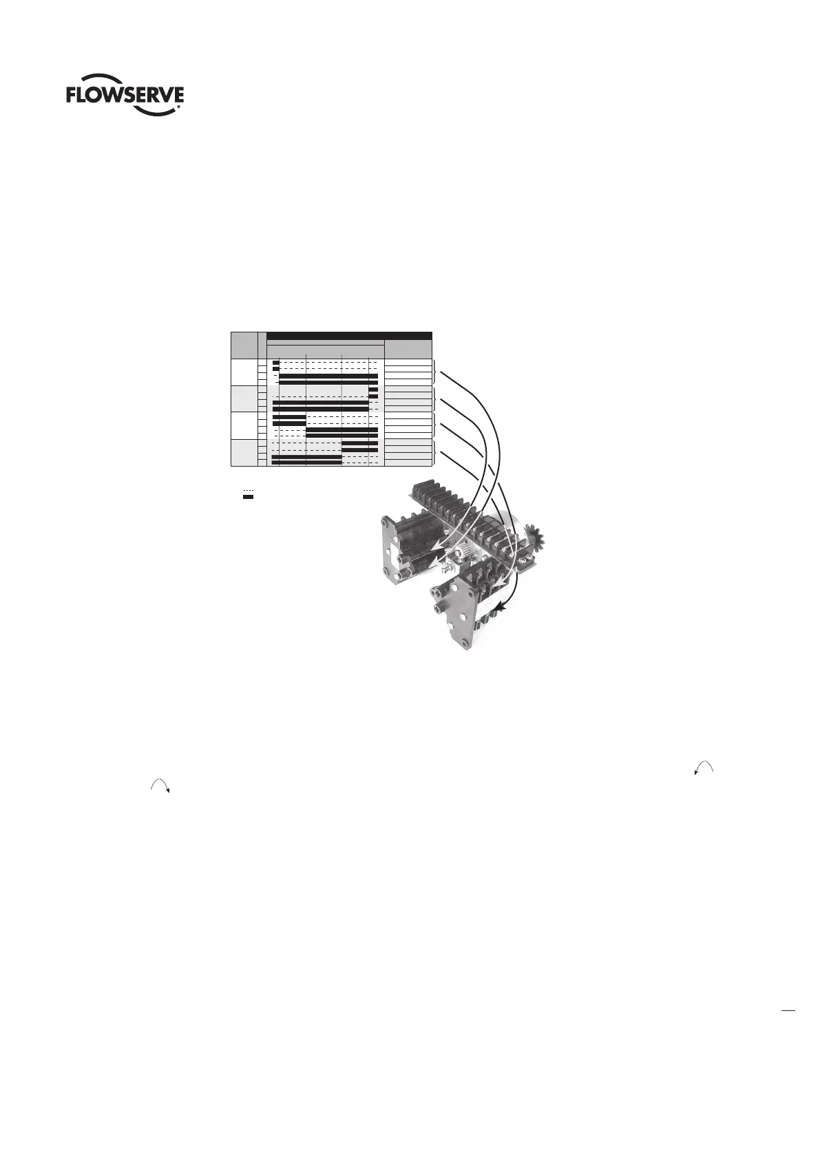
The standard L120-85 Limit Switch has 16 contacts. The OPEN/CLOSE Limit Switch (first eight contacts) has two Rotor Sets, one for the
OPEN position and one for the CLOSED position. Each Rotor Set has four electrical contacts which can be arranged in any combination of
normally OPEN and normally CLOSED. The SPARE Limit Switch (second eight contacts) has two additional Rotor Sets with four contacts
each that can be set to operate anywhere between the OPEN and CLOSE positions. These can be used to stop the valve in mid-travel or to
interlock with other equipment such as pumps, fans, mixers, etc. Refer to Figure 8.
Figure 8: Limit Switch Rotor Development
NOTES
1. Contact Open
2. Contact Closed
3. All limit switch trip points
are fully adjustable.
.
BY-PASS CIR.
IND LIGHT
OPEN LIMIT
BY-PASS CIR
IND LIGHT
CLOSE LIMIT
SPARE
SPARE
SPARE
SPARE
SPARE
SPARE
SPARE
SPARE
FULLY
OPEN
A
B
FULLY
CLOSED
VALVE SHOWN IN FULL OPEN POSITION
INDICATION
INDICATION
LIMIT SWITCH CONTACT DEVELOPMENT
VALVE POSITION
ROTOR
OPEN
CLOSE
INT.1
INT.2
FUNCTION
1
2
3
4
5
6
7
8
9
10
11
12
13
14
15
16
CONTACT
NOTE: THE LIMIT SWITCH IS NOT PRESET at the Limitorque factory, and must be set after mounting on the valve or other associated
equipment. If your L120-85 actuator has been shipped already installed on your equipment, your actuator should have the Limit Switch
set for your application. If your actuator is not already installed on your equipment or needs resetting, use the following instructions to
make the appropriate settings.
The following instructions for setting the Limit Switches are based on the typical orientation for most actuator applications (CCW to
OPEN and CW to CLOSE). Consult the applicable wiring diagram located in the actuator Electrical Compartment for your specific Limit
Switch development.
4.3.1 Basic Theory of Operation
c
WARNING: Do not manually operate actuator with devices other than installed Handwheel and Declutch Lever. Using additive force
devices (cheater bars, wheel wrenches, pipe wrenches or other devices of this nature) on the actuator Handwheel or Declutch
Lever may cause serious personal injury and/or damage to the actuator or valve.
c
WARNING: Hazardous Voltage. Make sure all power is OFF before opening the Electrical Compartment Cover or making the
following settings.
The Limit Switch (piece 305) is driven directly by the Worm Shaft through the Limit Switch Pinion. Therefore, the Limit Switch is directly
connected to the output of the actuator. Once the Limit Switch is properly set, it measures the position of the valve, or other equipment, in
the ELECTRIC or MANUAL operating modes.