17
Limitorque L120-85 Installation, Operation and Maintenance FCD LMENIM1202-03-A4 – 06/15
flowserve.com
a
CAUTION: The Worm on the Worm Shaft Assembly is available in two different ratios 19:1 and 38:1. To avoid damage to the
gearing mechanisms, be sure you change the Limit Switch Drive Pinion gear if the Worm gear ratio is changed.
NOTE: The Limit Switch is available with a 4 Gear Set or a 5 Gear Set within the Gear Frame Assembly. The number of Gear Sets built
into your specific Limit Switch will determine the number of maximum Drive Sleeve rotations required to go the full range of the Limit
Switch. A four Gear Set with 19:1 and 38:1 has a maximum rotation of 902.25 Drive Sleeve rotations. A five Gear Set with 19:1 and
38:1 has a maximum rotation of 9022.5 Drive Sleeve rotations.
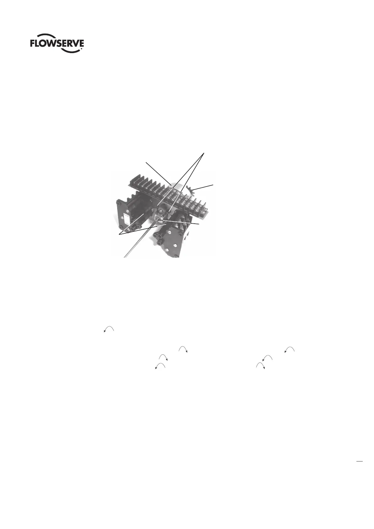
Figure 9: L120-85 Limit Switch Components
Gear Frame
Assembly
Intermediate Shafts
(A, B, C, and D)
Drive Pinion
Clutch Screw
Rotor Cams
4.3.3 Setting the OPEN Limit Switch
1. De-engerize the electrical circuit to the actuator.
2. Open the Electrical Compartment Cover (piece 200-1).
3. Put the actuator into MANUAL operation by moving the Declutch Lever in the direction of the arrow on the lever until the Declutch
Lever locks in place.
4. Turn the Handwheel CCW to move the valve to the full OPEN position. While turning the Handwheel, note the direction of the
Intermediate Shaft that corresponds to the Open Rotor Group. See figure 9.
NOTE: Most applications require turning the Handwheel CW to obtain the full CLOSE position and CCW to obtain full OPEN
position. The actuator Drive Sleeve rotates in a CW direction to the CLOSE position and CCW to the OPEN position. The
Limit Switch Intermediate Shafts rotate in a CCW direction to the CLOSE position and CW to the OPEN position. If your
application is configured differently, keep in mind that the descriptions in this manual will describe rotation directions opposite of your
application.
5. Once the valve is fully OPEN, turn the Handwheel back toward CLOSE approximately one full turn. This will allow for coasting during
motor operation.
a
CAUTION: Do not operate the actuator when the Clutch Screw is in a fully depressed position; loss of the contact setting will occur and
the Setting Rod will be damaged.