115
Limitorque MX Maintenance and Spare Parts FCD LMENIM2314-00 – 07/08
flowserve.com
• After enabling the Modutronic option, if digital inputs are used for control, remote control may be set
to user inputs.
• For adding the APT, ATT, and R options, the analog output board(s) and/or the digital output board(s)
will be required. When these board(s) are installed into the actuator, it will already have the option(s)
enabled. The unit will recognize the board and turn on the required software menu feature. Please
refer to the IOM manual, LMENIM2306, supplied with your actuator for the Menu sequence. The user
will need to enable the menu options. Please contact your assigned Service Coordinators for purchase
of these desired options at (434) 528-4400.
• For adding the DDC, FF, DN or PROFIBUS option, the DDC, FF, DeviceNet or PB option board is
required. When these boards are received and installed into the actuator, it will recognize the board
and turn on the required software menu feature. Please refer to the IOM manual, LMENIM2306,
supplied with your actuator for the Menu sequence. The user will need to enable the menu options.
Please contact your assigned Service Coordinators for purchase of the network options at (434)
528-4400.
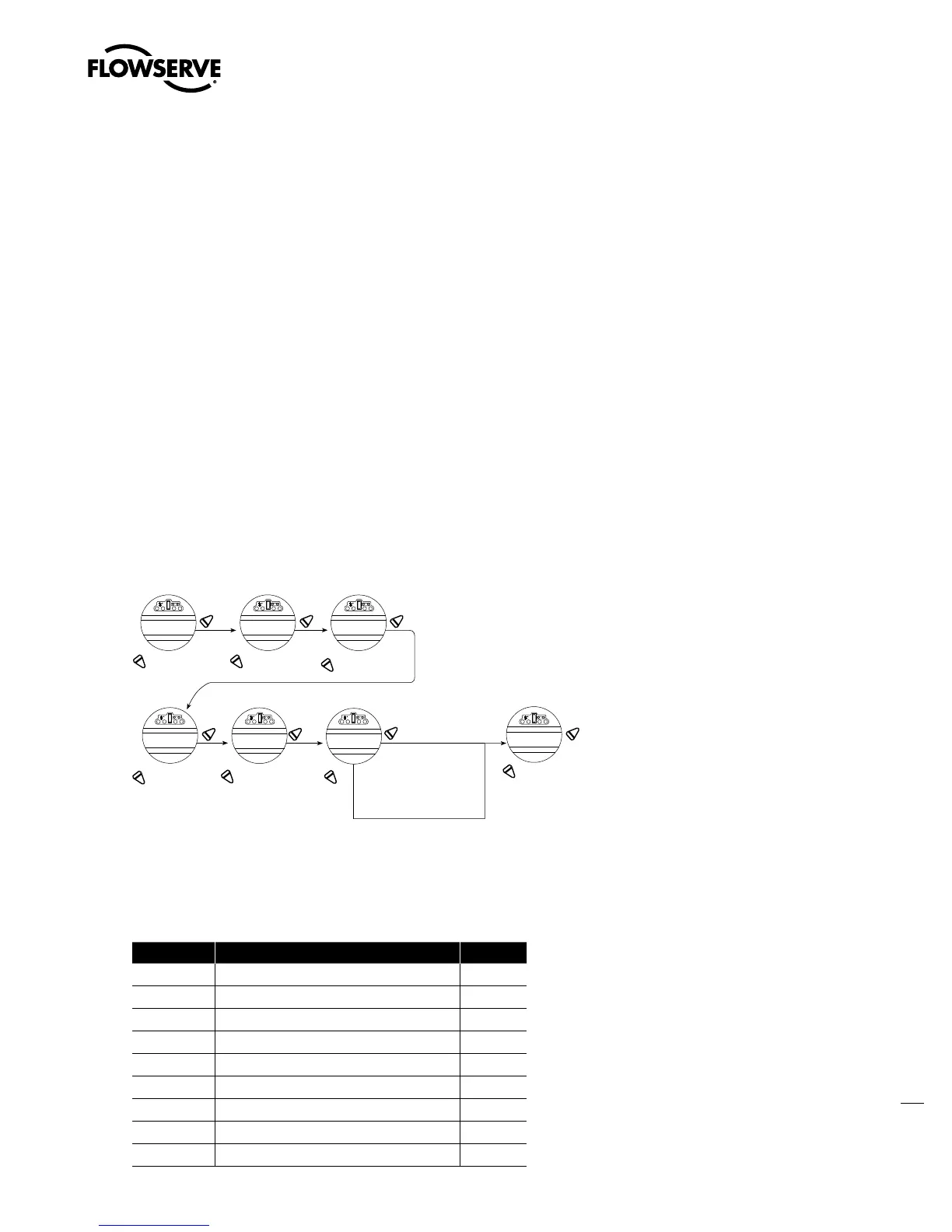
5.7 Restoring Power to Actuator
with New Control Module
Figure 5.11 – Restoring Power to Actuator with New Control Module
YES
NO NO
YES
NO
YES
YES
YES
NO
NO
YES
NO
UNIT SIZE
MX-05-OK?
VOLTAGE
460 VOLT-OK?
Hz
60 Hz-OK?
ACTUATOR RP M
12/18-OK?
S/N
0------OK?
COLD (-50°C) UNIT
YES/NO -OK?
INITIALIZE?
Answer “ NO ” until the
correct unit size is
displayed. Refer to
nameplate.
Answer “ NO ” until
the correct voltage
is displayed. Refer
to nameplate.
Answer “ NO ” until
the correct frequency
is displayed. Refer to
nameplate.
Answer “ NO ” until
the correct rpm
is displayed. Refer
to nameplate.
Answer “ NO ” until the
value is displayed and
then “ YES ” to enter .
Refer to namplate for
S/N.
Answer “NO” to
select normal
temperature
parameters,
-22°F to +158°F
(-30°C to +70°C).
Answer “YES” to select arctic
temperature parameters,
-58°F to +140°F (-50°C to
+60°C).
Please refer to Limitorque
MX Customer Connection(s) Diagram
(#L2180) reverse side (located on the
inside of the terminal compartment
cover) for customer default
configuration.
Answer
“NO” to
change.
Answer “YES”
to save settings.
NO
YES
5.8 Terminal Block (prior to March 2007)
Table 5.5 – Terminal Block Parts List
Part Number Description Qty.
1-20 O-ring 1
1-21 Retaining ring 1
1-43 Pan head (M3x4) plastic screw 2
8-15 Terminal block 1
8-16 Self-lock combo head screw (M3x5) 48
8-17 Self-lock combo head screw (M5x8) 3
8-18 Cover plate 1
8-19 Pan head self-tapping screw 2
8-20 Control wiring harness 1
Swanson Flo | 800-288-7926 | www.swansonflo.com