43
Digital Communication Interface
Wiring
6 Digital Communication Interface
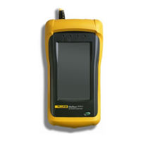
The 1523/24 handheld readout is capable of communicating with and being controlled
by an external device through the RS-232 digital interface.
With a digital interface, the instrument may be connected to a computer. This allows
the user to obtain measurement data and control operating conditions. The RS-232 se-
rial interface allows serial digital communications over fairly long distances. With the
serial interface, the user may access any of the functions, parameters and settings dis-
cussed in this section. The 9940 software that came with the unit is available to assist
in the communications interface. Refer to the documentation included on the software
CD for additional information.
Special Note on Using grounded and bare junction thermocouples with
RS-232:
Special precautions should be taken when using RS-232 communications with the
1523/24 and a grounded thermocouple or bare junction thermocouple. A grounded
thermocouple has its measurement junction electrically connected to a conductive
sheath and a bare thermocouple has an exposed measurement junction. Both thermo-
couple congurations may expose the circuit to potential ground loops and electrical
interference when the 1523/24 is connected to a personal computer through an RS-232
cable. The effect may vary from setup to setup depending on the computer and the
overall system.
Ground loops and electrical interference may result in inaccurate measurements if
proper precautions are not taken. These precautions involve breaking an undesired
electrical connection to ground or to the computer. The following are examples of
precautions that may be taken:
1. Use the 1523/24 demand log and auto log functions to avoid connecting to a
computer when using grounded junction or bare junction thermocouples. Once
the readings are complete, connect the RS-232 cable and upload the data to the
personal computer.
2. Use an optically coupled isolator that is connected between the personal
computer and the RS-232 cable to the 1523/24. The Isolator breaks the
electrical ground loop by only communicating data, using light. Refer Section
1.8 for contact information to purchase the Isolator or if you have any further
questions.
3. Use a laptop computer running on its battery without an AC adapter. This may
provide enough isolation to minimize the grounded thermocouple measurement
errors. The user should test this scenario by taking measurements with and
without the RS-232 cable connected to the 1523/24.
6.1 Wiring
The serial communications cable attaches to the instrument through the 1/8” mini-jack
connector at the top of the instrument. To reduce the possibility of electrical interface,
Shop for Fluke products online at:
1.877.766.5412
www.MyFlukeStore.com