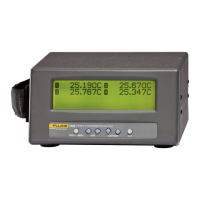
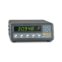
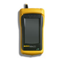
1523, 1524 Reference Thermometer
Manual Calibration
78
Table 25 Test Equipment Specifications
Classication Minimum Use Recommended Equipment
Voltage Source ± 6ppm ± 0.6uV Fluke 5700
4 wire Reference Resistors See Total Uncertainty column
Table X
Vishay VHP100 Resistors
4 wire cable Low resistance, Low EMF N/A
Lemo Connector 6 pin LEMO PAG.M0.6GL.AC39G
Table 26 Standard Reference Resistor Specification
US1 (k=2) US2 (k=2) UT (k=2)
Resistance
Reference
Resistor
Uncertainty
(ppm)
Reference
Resistor
Uncertainty (Ω)
TCR
Uncertainty
(ppm)
TCR
Uncertainty (Ω)
Total
Uncertainty (Ω)
Total
Uncertainty
(ppm)
0 -- 0.00004 -- -- 0.000540 --
25 28 0.0007 0.3 0.0000075 0.000700 28.0016
75 15.73 0.00117975 0.3 0.0000225 0.001180 15.7329
100 14 0.0014 0.3 0.00003 0.001400 14.0032
200 11.5 0.0023 0.3 0.00006 0.002301 11.5039
400 10.25 0.0041 0.3 0.00012 0.0041 10.2544
10000 35 0.35 0.3 0.003 0.3500 35.0013
40000 26.25 1.05 0.3 0.012 1.0501 26.2517
100000 74 7 0.3 0.03 7.0001 70.0006
300000 70 21 0.3 0.09 21.0002 70.0006
500000 70 35 0.3 0.15 35.0003 70.0006
Table 27 Standard Voltage Reference Specification
Voltage mV
Reference Voltage Total
Uncertainty (mV)
–10 0.00125
0 0.00110
25 0.00145
75 0.00210
7.7 Manual Calibration
7.7.1 General
This procedure outlines a manual process that closely follows the way the Reference
Thermometer was calibrated at the factory. The user should adjust their calibration
process to meet the needs of their facility and process. The following ow charts sum-
marizes the process.
Shop for Fluke products online at:
1.877.766.5412
www.MyFlukeStore.com

 Loading...
