Electrical Installation Tester
Operating the Tester
7
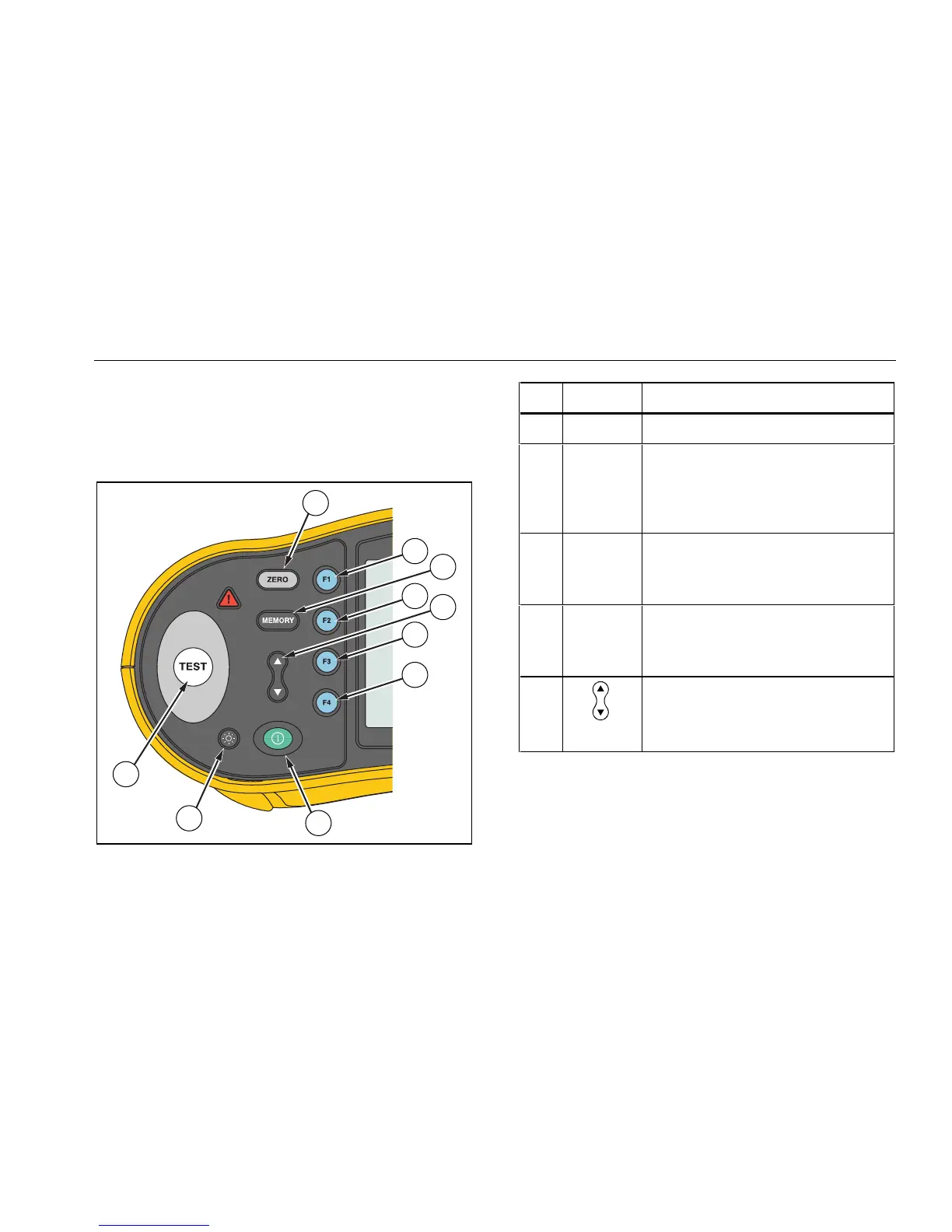
Understanding the Pushbuttons
Use the pushbuttons (Figure 2) to control operation of the
tester, select test results for viewing, and scroll through
selected test results.
9
10
1
8
2
4
5
3
6
7
apx012f.eps
Figure 2. Pushbuttons
No. Button Description
A Z Zero test lead resistance offset.
B 1
• Loop input select (L-N, L-PE).
• RCD current rating (10, 30, 100,
300, 500, or 1000 mA).
• Memory SELECT.
C M • Enters Memory mode.
• Activates memory soft key
selections (1, 2, 3, or 4).
D 2 • RCD Current multiplier (x1/2, x1,
x5, AUTO).
• Memory STORE.
E • Scroll memory locations.
• Set memory location codes.
• Scroll Auto test results.