1732/1734/1736/1738/3540 FC
Calibration Manual
12
Equipment Assembly
The 173x calibration cables and verification box are not available from Fluke. If you plan to calibrate your
Product rather than send it to a Fluke Service Center, use the assembly instructions that follow.
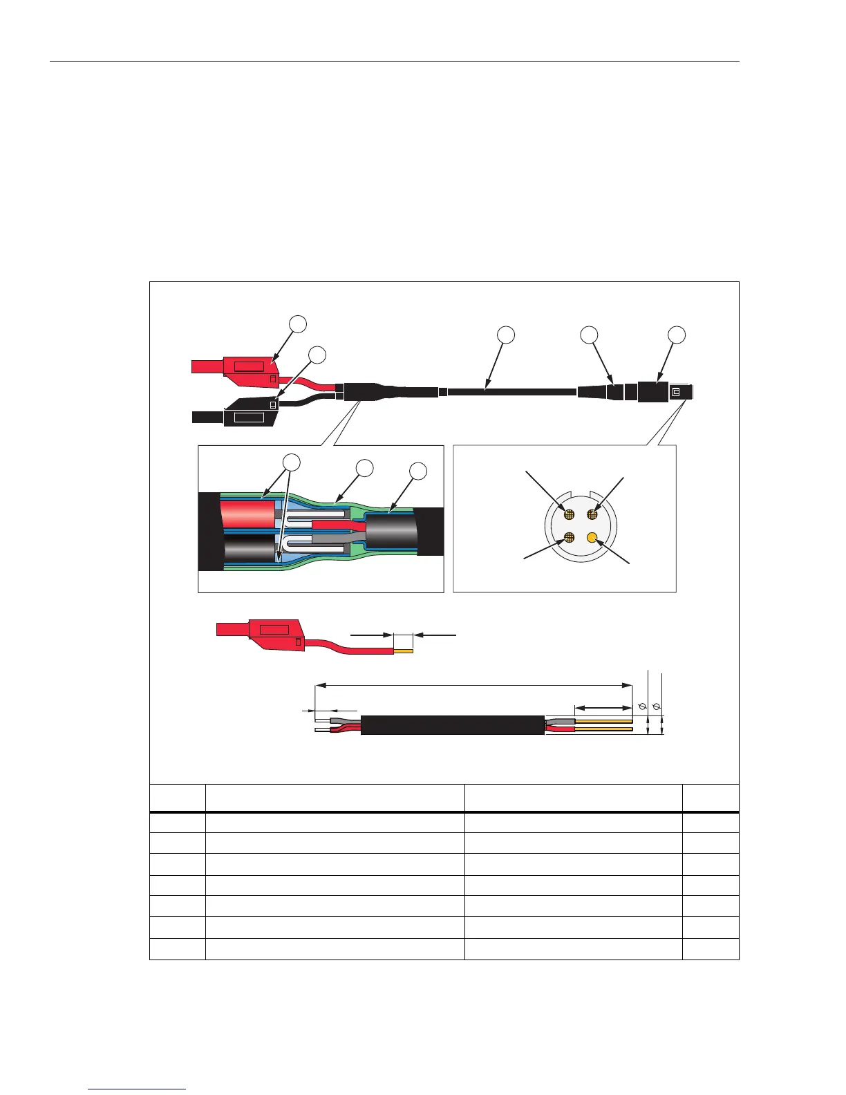
173x Calibration Cable Assembly
See Table 4 for instructions on how to make the calibration cables.
Caution
Cable must be marked with “max. 30 V to earth.” Any voltage-, category-, or current-
ratings on safety plugs must be removed.
Table 4. 173x Calibration Cables, Voltage-to-Current-Input
hcf104.eps
Item Description Part Number/Info QTY
Straight Plug, IP50, 4-Pole ODU: S21M08-P04MJG0-528S 1
Cable Bend Relief ODU: 701-023208965-040 1
Signal-Cable, 2x AWG 22-24, shielded
∅4-5 mm (Fluke equiv. # 3803634)
1
Test Lead with 4 mm Safety Plug, stackable red 1
Test Lead with 4 mm Safety Plug, stackable black 1
Heat Shrink Tubing, 2:1
∅=4.8 mm (3/16”); L=35 mm
3
Heat Shrink Tubing, 3:1, adhesive
∅=12 mm (1/2”); L=60 mm
1
10
+
2
0
1930
±10
15
±1
4
-
0
1
5 max.
4 min.
Screen
(Pin 4)
N.C.
(Pin 3)
Red Wire
(Pin 1)
Black Wire
(Pin 2)
123
4
5
6
7
6

 Loading...