Logger/Monitor
Optional Verification for Flexi or Clamp (Combined Logger and Probe Specifications)
23
AUX Input Check (1732/1734/1736/1738 Only)
1. Connect 173x AUX input calibration cable to the Logger AUX inputs.
2. Stack the two red banana plugs together and connect them to the calibrator Normal HI.
3. Stack the two black banana plugs together and connect them to the calibrator Normal LO.
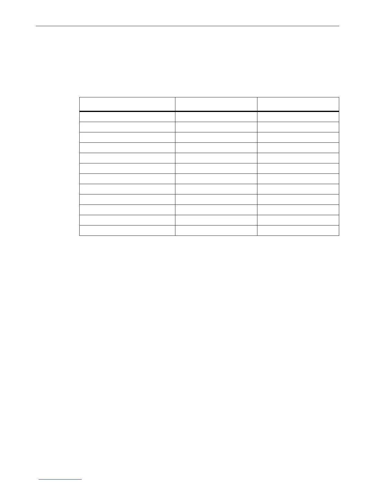
4. For all the voltages in Table 12
, set the calibrator and check that the values are between the limits.
Table 12. AUX Input Verification
5. Set the calibrator to Standby.
Optional Verification for Flexi or Clamp (Combined Logger and Probe Specifications)
This feature of the spreadsheet checks the Logger combined with current probes. These tests use the 552x
and the 5500 Coil, or the 52120A Coil as an option. The Test Uncertainty Ratios (TUR) is typically <2:1. This
system can only source 1000 A, consequently, this test will not be made at full-scale of the Flexi probes.
To connect the customer current probes to the Logger:
1. Connect the VL1730 "N" lead to the calibrator NORMAL LO.
2. Connect the calibrator NORMAL V output to the VL1730 L1+L2+L3 leads.
3. Connect the calibrator AUX jacks:
• For the 5500 Coil verification (see Table 13) connect the 5500 coil to the calibrator and the black jack to
AUX LO. For a i40S-EL clamp, connect a 5-turn coil to the calibrator. Connect the red jack to either the
AUX jack when <3 A is requested or the 20 A jack when >3 A is requested.
• For the 52120A Coil verification (see Table 14) connect calibrator AUX HI and LO to the 52120A
INPUT HI and LO.
4. Connect the current probes under test:
• For the 5500 Coil verification through the 5500 Coil with arrows pointing up for the correct phase match.
• Pass the Flexi, or clamp under test through a single loop, or 3 KA coil, or 6 KA coil, with arrows pointing up
for the correct phase match as indicated in the table.
5. The spreadsheet Verification tab has an Attached Sensor drop-down list box to select the probe that is
connected.
Calibrator Out DC Volts Upper Limit Vdc Lower Limit Vdc
-10.0000 -9.9780 -10.0220
-5.0000 -4.9880 -5.0120
-1.0000 -0.9960 -1.0040
-0.5000 -0.4970 -0.5030
-0.1000 -0.0978 -0.1022
-0.0100 -0.00798 -0.01202
0.0100 0.01202 0.00798
0.1000 0.1022 0.0978
0.5000 0.5030 0.4970
1.0000 1.0040 0.9980
5.0000 5.0120 4.9880
10.0000 10.0220 9.9780

 Loading...