Logger/Monitor
Setup
15
Verification Box Assembly
This Verification Box provides more accurate voltages than a direct connection to the 5520A. The 5520A
uses a divider with a 50 Ω output impedance when sourcing <330 mV. Due to variations in the Logger input
impedance, the actual applied voltage is less than the programmed voltage. Using an external divider where
the parallel resistance is ~30 Ω allows calculation of the applied voltage with confidence that the Logger
input loading will not significantly impact the applied voltage.
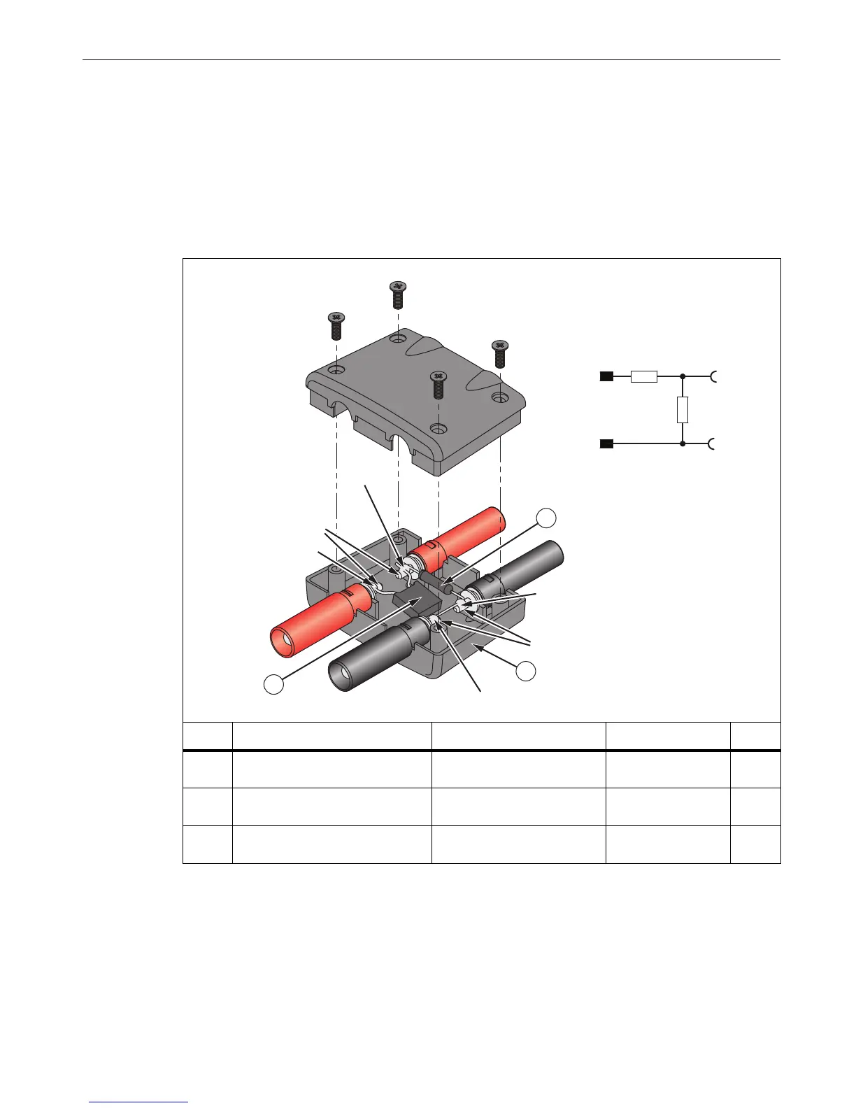
Fluke recommends using a verification box that has a divider with 30 Ω across the Logger input and 10 kΩ in
series with high side of the input. See Table 6 for instructions on how to make the verification box.
Table 6. 1730 Verification Box
hcf105.eps
Item Description Part Number/Info Fluke Part Number QTY
Multi-Contact Box: MA 524
Type: XKH-4/19/A
Order-No.: 66.9045-33
NA 1
Resistor, Metal Foil 10 kΩ,
±0.1 %, 0.6 W, ±4.5 PPM
Red Plug/Red Socket 2114858 1
Resistor, 30 Ω, 1W, 1% 20 PPM
Red Socket/Black Socket +
Bridge Black Plug/Socket
1757740 1
2
3
1
Contacts Pretinned
Contacts
Pretinned
Red Plug
Red
Socket
Black Socket
Black Plug
Soldered
Soldered
Soldered
Soldered
10 k
30 Ω
Red
Black Black
Red

 Loading...