Logger/Monitor
Accuracy Verification Procedure
21
Accuracy Verification Procedure
The procedure verifies the Power Logger accuracy at ambient temperature 23 °C ±2 °C (intrinsic error).
A complete accuracy verification of the Fluke 173x consists of:
• Voltage Measurement
• Current Measurement
• AUX Measurement
• Optional Flexi or Current Clamp Verification
Voltage Measurement
1. Select the setup. See Basic Instrument Setup for all Verifications.
2. Connect the VL1730 "N" lead to the calibrator NORMAL LO.
3. The Logger must be on battery power with ≥50 % charge.
4. Connect the calibrator NORMAL V output to the VL1730 L1+L2+L3 leads.
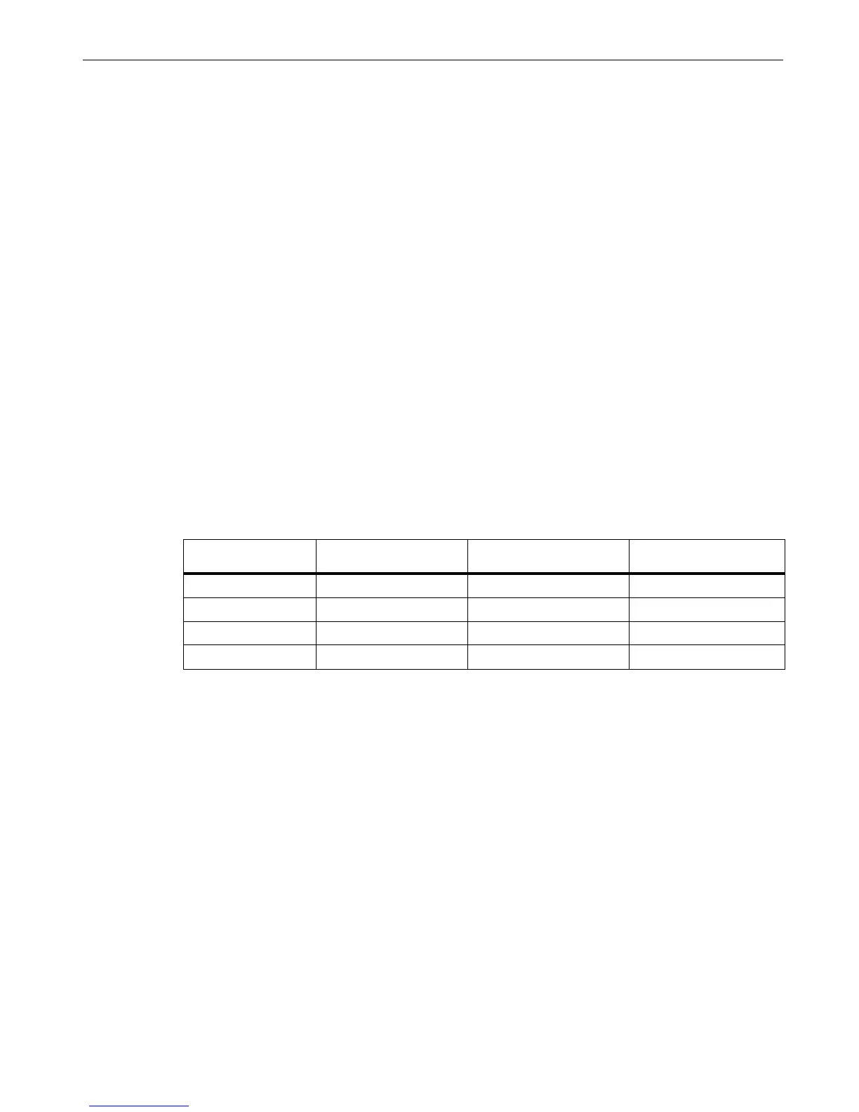
5. Sequentially set the calibrator to the voltages indicated in Table 10 and check that the Logger reading is
between the limits.
6. Do this for all ranges indicated in Table 10:
• set the calibrator to supply a 57.0 Hz sine wave for all voltages
• wait until each reading has stabilized
The spreadsheet is the first choice for readings. Readings will have more resolution from the
spreadsheet.
7. Push to select the Power Logger voltage display.
Table 10. Voltage Verification
8. When you are done, set the calibrator to Standby.
Nominal Voltage
(Range)
Calibrator voltage
(57 Hz sine wave)
Minimum Reading
± (0.2 % + 0.01 %)
Maximum Reading
1000 10 9.9 10.1
1000 100 99.7 100.3
1000 500 498.9 501.1
1000 1000 998 1002

 Loading...