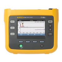
1732/1734/1736/1738/3540 FC
Calibration Manual
28
Calibration Adjust Procedure
This procedure adjusts the Logger accuracy at ambient temperature 23 °C ±2 K (intrinsic error).
The required equipment and cables for calibrating the Product are listed in Table 3. See USB
Communication for instructions on how to set up the PC.
Warning
To avoid electrical shock, personal injury, or fire:
•
Do not perform the calibration procedures or calibration verification tests
described in this manual unless you are qualified to do so.
•
Repairs or servicing should be performed only by qualified personnel.
The spreadsheet contains an automated adjust in the Calibration & Verification worksheet. When used, it
provides connection instructions, can control the calibrator to apply the required voltage, and then will
calculate and store the new calibration factors.
When this worksheet is active, the selection box should pop up. If not, click the Start button on the upper
right of the worksheet.
In the Setup tab, only the calibrator control needs to be set (the Voltage divider is not used in the 173x
Adjust).
Select the Calibration tab of the 173x Calibration & Verification pop-up. Choose Voltage, AUX, or Current
calibration and check the boxes to select items for adjustment.
1. When selection is complete, click Start.
2. Follow the instructions provided in the automated procedure.
Note
The calibration adjust of the 3540 FC is done on the phase currents
L1/A, L2/B, L3/C. Adjustment of the plugged neutral current is not supported.
When the 173x Calibration & Verification popup box shows again, the calibration factors have been
calculated and stored in the Logger.
This concludes the calibration.

 Loading...