Logger/Monitor
173x Auxiliary Input Adapter Verification (1732/1734/1736/1738 Only)
27
Additional Errors:
Influence by galvanic connection of sources
1. Connect the 4-pin connectors AUX 1 + (pin 1) to the 8846A INPUT HI.
2. Connect the 4-pin connectors AUX 1 – (pin 2) to the 8846A INPUT LO.
3. Connect the 173x AUX Adapter box AUX 1 + and AUX 2 + to the calibrator Normal HI
4. Connect the 173x AUX Adapter box AUX 1 – and AUX 2 – to the calibrator Normal LO.
5. Set the 8846A to DC V.
6. Apply the voltages in Table 17.
7. Verify that the AUX 1 readings are between the limits.
8. After the values are checked for AUX 1, move the 4-pin connectors leads to AUX 2; Pin 3 to the 8846A
INPUT HI; pin 4 connected to the 8846A INPUT LO.
9. Apply the voltages in Table 17. Verify that the AUX 2 readings are between the limits.
Table 17. AUX Input Adapter Verification
Note
The limit values account for input loading of a 10 MΩ input on the DMM compared to
2.92 MΩ impedance of the 173x Logger. The effective scale factor changes from
1000:1 to 741.01:1. The error on the output of the Auxiliary Input Adapter is
±(0.7 % + 270 μV).
10. When finished, set the calibrator to Standby.
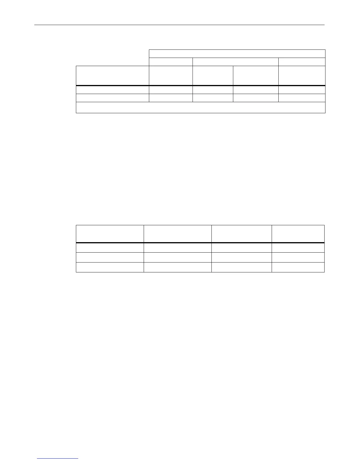
Typical additional errors for measurements on galvanic-connected sources
2x Divider Inputs Divider Input/Direct Input 2x Direct Inputs
Type of Influence
AUX1 or AUX2
1000 V CAT III
Input
AUX1 & AUX2
1000 V CAT III
Input
AUX1 or AUX2
max 30 V to
ground Input
AUX1 or AUX2
max 30 V to ground
Input
Common Mode [1] 1.5 % of VCM 3 % of VCM 30 ppm of VCM 0.15 % of VCM
Voltage difference [2] 0.7 % of Vdiff 1.5 % of Vdiff 15 ppm of Vdiff 0.15 % of Vdiff
[1] Common Mode Voltage VCM = Voltage difference between LO potentials of AUX1 and AUX2
[2] Voltage difference Vdiff = difference of voltages VAUX1-VAUX2 with connected LO terminals
Calibrator Out DC Volts
Nominal Output Vdc
Aux Adapter
Lower Limit Vdc Upper Limit Vdc
100.000 0.13495 0.13374 0.13617
500.000 0.67475 0.66976 0.67975
990.000 1.33601 1.32639 1.34564

 Loading...