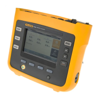
Logger/Monitor
Setup
13
173x AUX Input Calibration Cable
See Table 5 and Figure 1 for instructions on how to make the calibration cable.
Caution
Cable must be marked with “max. 30 V to earth.” Any voltage-, category-, or
current-ratings on safety plugs must be removed.
Table 5. 173x AUX Input Calibration Cable
Item Description Part Number/Info QTY
Binder: Series 620 - Male Cordset, 4-pole, 2 m Binder: 79 9241 020 04 1
Test Lead 0.75 mm² with 4 mm Banana Plug, stackable red 2
Test Lead 0.75 mm² with 4 mm Banana Plug, stackable black 2
Shrink tube Ø 5-6 mm, black, thin wall, 3:1 L = 30 mm 4
Shrink tube Ø 8-10 mm, transparent, thin wall, 2:1 L = 45 mm 2
Shrink tube Ø 10-12 mm, black, thin wall, adhesive, 3:1 L = 30135 1
Shrink tube Ø 12-14 mm, black, thin wall, 3:1 L = 110 mm 1

 Loading...